All in One PCB

For those who want avoid crimping wires, or don’t have the correct tool, the AMP connector can be bought pre-wired

3 Likes

To bad the teensy 4.1 is going out of stock almost everywhere :frowning:

Available directly from the manufacturer pjrc…:man_shrugging::man_shrugging:

Will check out

I just got a standard F9P AMPSEAL PCB from JLCPCB the other day. I installed teensy, but on the serial monitor ADC CONECTON failed! is displayed and cannot be recognized. When Bno085 is connected, the LED shines and it is recognized by the serial monitor. Since there is no recognition of ADC, it is displayed as aotosteer disable, gps only mod. I supplied 12v to 22pin, but nothing changed. None of the 3 LEDs on the PCB light up.
Am I missing something?

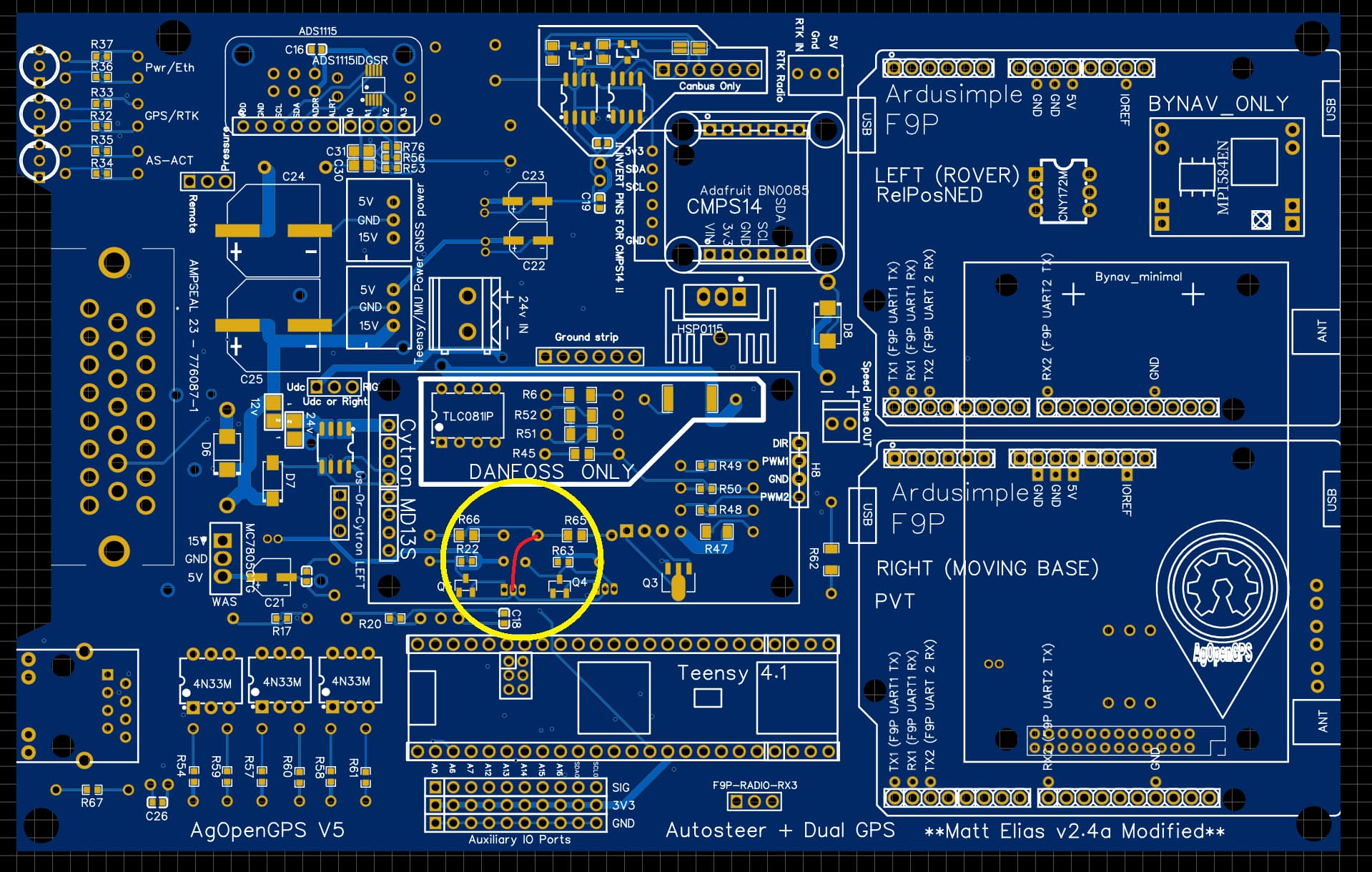
You need to solder in a jumper as marked. The PCB has a bug/glitch where the WAS I2C level shifters aren’t getting 3.3V reference. I’d recommend it from the back side. @kazu

2 Likes

@m_elias Thank you. I was able to solve the adc problem.
Even the serial monitor recognizes it.
But I got the following problem. I put f9p on it and tested it, but the LED on the PCB still doesn’t light up. panda is working but doesn’t recognize anything else. From teensy, no output to pwr/EthLED. For teensy I booted Autosteer_gps_teensy_v5_5 from the latest 5.6.16 support files.
Also, am I missing something?


I know the answer. All I had to do was change the IPAddress ipDestination in autosteer.ino. thank you everyone.

Micro_Screws.zip (3,1 MB)

Fixed desing box for micro

Original Box

Fixed Box

3 Likes

Can you share the file as a dwg or other cad file?

There are six models, which one do you want?

Micro, screws and deutsch connector box.
Thanks a lot!

All_In_One_Jake_Screw v3.zip (4,3 MB)

2 Likes

I’m using a single F9P, the Panda firmware for F9P is only for Dual heading only?

for me the firmware works with both setups. I started with just one F9P+imu and it worked. after that, I added the second F9P and changed setting to Dual. works also.

1 Like

*.step is as bad as *.stl for my autocad.

Micro_3Dprint.zip (1,4 MB)

Micro_Screws.zip (3,1 MB)

Fixed SMA Holes for Micro (only changes covers), hole for right micro slot, and corrected height from PCB

DWG file

1 Like

I think something is wrong on the board. I got 12v on pin 1 simpleRTK2B Micro. It was really getting hot :frowning:
Looking at print i have no idea what could be wrong. Any one have idea? I have the micro all in one AMP board.

Lookslike i have a faulty K7803. On the 3,3v output i have 12V :frowning:

Hope my micro rtk board is ok.

test a regulator and make sure it is not backward.
There are some chinese regulators that the pinout is reversed