All in One PCB

You only need that for ByNav.

And the diode cannot be put there, even on the side. After the track is cut.

But basicly if you always take the teensy of before programming or not use external.power to read teensy serial there is no harm in leaving it like it is?

I myself always remove teensy from board when uploading new .ino file. And check serial output without powering pcb.

3 Likes

Yes that would be fine.

I don’t think this is strictly necessary. I reviewed the documentation and they make it sound like cutting that trace is only required if you want to power the board on lower or higher-voltage source, such as a battery. If Vin is approximately 5v, there’s probably no problem with the usb power being hooked up at the same time. I’ve done it for years this way.

EDIT: I have read just now of cheap powered USB hubs backfeeding some voltage and causing some issues (mostly causing motherboard usb ports to stop working temporarily), so I guess if you’re worried, better safe than sorry.

1 Like

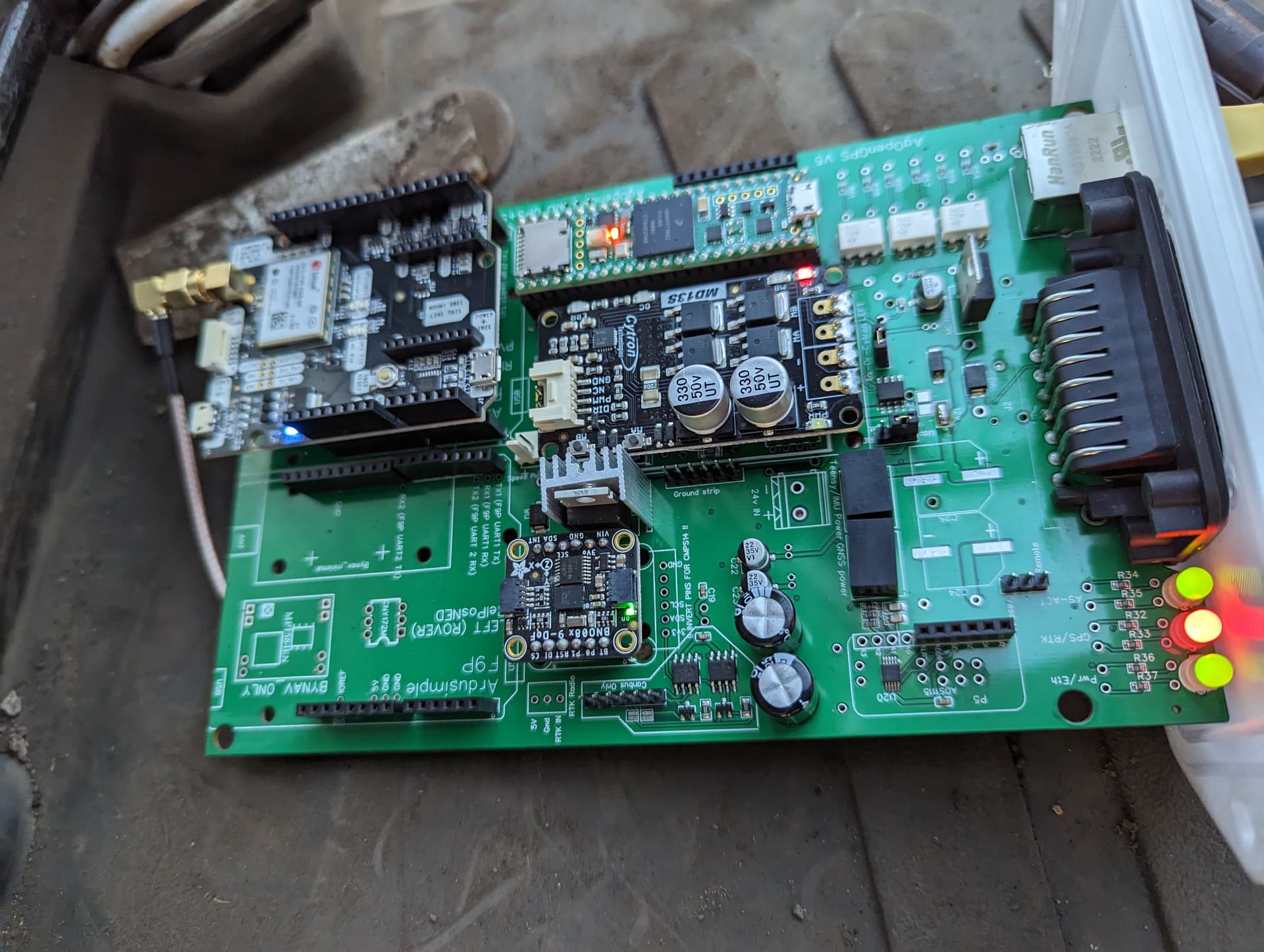
Just in the process of wiring up my AIO board. Using AOG v5.7 and the latest ino.
I am getting RTK Fix In AOG, sentence seems to be correct yet the RTK led on the PCB stays red. Is there any possible reason for this?
Thanks

1 Like

In the AIO standard Q3 is a BJT NPN transistor, it’s out of stock at JLCPCB, struggling to find a perfect match spec for spec, is the following suitable? @Jhmach

Top picture is the actual Q3 from JLCPCB, bottom picture is closest THT I’ve found, the 2N3705 variant.


This is the tht equivalent
In easyEDA, if you right click on the green THT part in the trace with the SMD it will give you the part numbers

1 Like

MOTOR Guys
I have edited the Micro PCB and made the traces heavier for the motor guys. Also have removed the CAN bus components and suppressed the Danfoss components, for a more basic all in one for the motors.
It is newly finished and untested, though there are not a lot of changes. To run motors it will need some 16 gauge insulated wires soldered in as jumpers since there is no board space left to get the traces large enough for the higher currents.


The light blue lines from R/L to the cytron.
The other light blue line is for using 12V in from the board power. If using external 12V or 24V, use the darker blue path and power the cytron at pin 16 of the AMP connector. The 24V jumper will need soldered for all motors and the 12v must be left unsoldered.

https://drive.google.com/drive/folders/1usCFJvlXnaOCqDf0f4bx8o_yOgFUw9XZ?usp=share_link
EDIT
NO more solder jumpers. The google link has been updated


EDIT
Labels on Left/Us and Lock/Right were corrected
Google Drive is updated

2 Likes

I think there’s a slight silkscreen error on the micro board.
image
The cytron Us-or-Cytron LEFT should be the other way round, i.e. Cytron LEFT-Or-Us.
It’s correct on the standard board. Same problem with LOCK or RIGHT by the looks of it.

It just means the jumper needs to be the other way round

I changed it and didn’t save it again. I will fix it. Thanks

Edit
Labels Fixed

Correction only for the micros or for the standards?

I haven’t looked at the standard, but I should.

2 Likes

Anyone selling the all in one pcb for the big f9p
?

I have a few left with the Ampseal23 connector & harness. I mostly ship to Canada and the US. If you’re interested, send me a PM and I’ll get you pricing details.

edit
I’m all out of PCBs

2SC2884Y (JLCPCB Part#C475474) will be a suitable replacement for smd?

If it helps others, this is the correct part to substitute Q3 on the Standard AIO PCB, from Digi-Key,

2 Likes

Just kinda curious. But why did they chose to use all of those separate modules and through hole components? Wouldn’t it have been more compact and cost effective to replace most of them with SMD components?

Because these days, half the time you can’t get all the smt parts, so now at least there’s still the tht parts to getting it going.

I am getting RTK Fix In AOG, sentence seems to be correct yet the RTK led on the PCB stays red. Is there any possible reason for this?

I’m getting the same…from the code:
#define GPSRED_LED 9 //Red (Flashing = NO IMU or Dual, ON = GPS fix with IMU)
#define GPSGREEN_LED 10 //Green (Flashing = Dual bad, ON = Dual good)
So it will be solid red for single setup like us.
If the dual receiver guys flexing on you offends you then you could modify the code below by swapping the high and low. (zHandlers tab)

*if (!useDual)*
*       {*
*        digitalWrite(GPSRED_LED, HIGH);    //Turn red GPS LED ON, we have GGA and must have a IMU     *
*        digitalWrite(GPSGREEN_LED, LOW);   //Make sure the Green LED is OFF     *
*       }*