Where are you guys positioning the AIO board in the cab? Is under the seat best if possible for best IMU performance?
has anyone in the uk has order the new all in one pcb the standard F9P all in one ampseal
Hello,
Does anyone have the schematic of the standard All In One PCB?
1 Like
Its in the Backup folder at the top of this thread:
Do you not think that by bypassing the ACS712, you’re missing a feature that could negate the need to bypass the PCB for Cytron in/out.
The Phidgets draws 2.2 amps at full rated current, in most steering cog configurations, how hard is the motor really working? I’d say not very, sure there are lots of startup in rush currents which will be around the stall current of the Phidgets, 10.8A, but only for a tiny fraction of a second. In normal operation the motor is only working for a second or two in each direction and its only when doing a U-turn that the motor may run for several seconds continuously.
Setting the ACS712 slider in AOG to disengange steering when the load rises above normal levels, will surely act as ‘circuit breaker’ protecting the PCB from high currents? Whilst also protecting the steering cogs and mounts etc…
I’ve made some PCB’s as you have bypassing the PCB, but have one as stock and thinking in the future as long as you set the ACS712 accordingly then all should be well?
3 Likes
I agree with your reasoning. My bypass approach is a measure of precaution which might be exaggerated. The fact that I built 25 boards and most of them will be used by other farmers made me more cautious. If it was just for me, I might have chosen the way your pointing out
1 Like
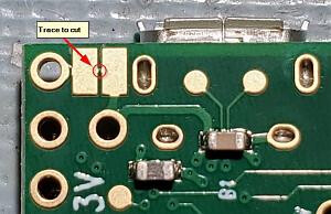
Everyone needs to cut the trace between Vin and Vusb on the Teensy before attaching the Teensy to any board.
If a board is powered and the Teensy USB is connected to a tablet or computer, which is has been powered down, it could damage the computer by back feeding power through the USB.
Some of these instructions are also posted on the WIKI
1 Like
What is a replacement for the MP1584EN. MP1584EN is not available at JLCPCB.
You only need that for ByNav.
And the diode cannot be put there, even on the side. After the track is cut.
But basicly if you always take the teensy of before programming or not use external.power to read teensy serial there is no harm in leaving it like it is?
I myself always remove teensy from board when uploading new .ino file. And check serial output without powering pcb.
3 Likes
Yes that would be fine.
I don’t think this is strictly necessary. I reviewed the documentation and they make it sound like cutting that trace is only required if you want to power the board on lower or higher-voltage source, such as a battery. If Vin is approximately 5v, there’s probably no problem with the usb power being hooked up at the same time. I’ve done it for years this way.
EDIT: I have read just now of cheap powered USB hubs backfeeding some voltage and causing some issues (mostly causing motherboard usb ports to stop working temporarily), so I guess if you’re worried, better safe than sorry.
1 Like
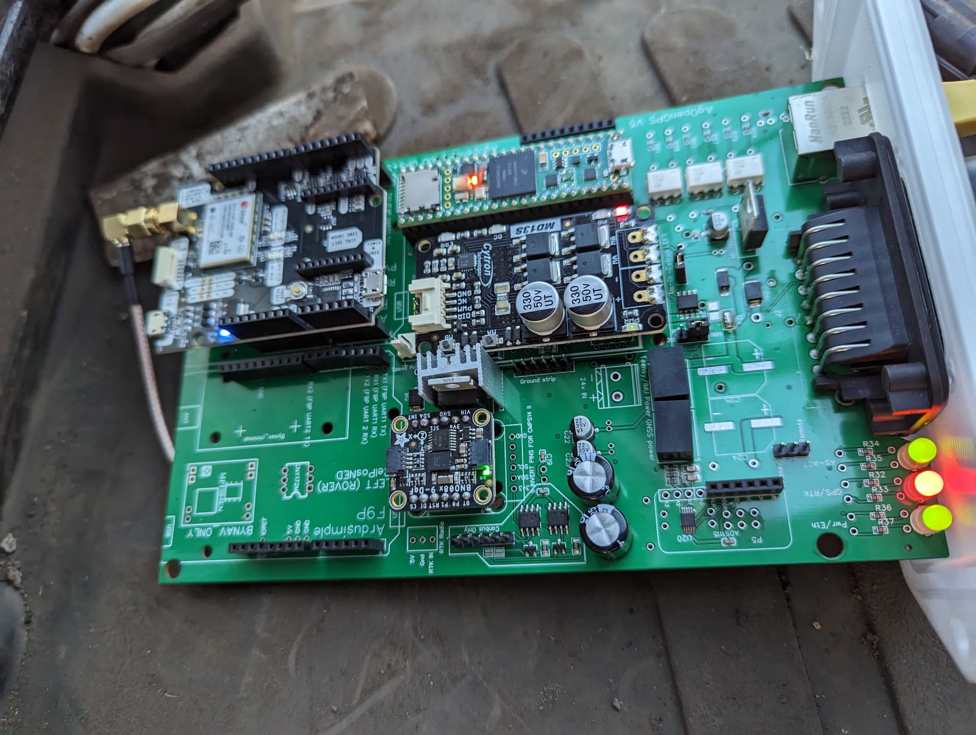
Just in the process of wiring up my AIO board. Using AOG v5.7 and the latest ino.
I am getting RTK Fix In AOG, sentence seems to be correct yet the RTK led on the PCB stays red. Is there any possible reason for this?
Thanks
1 Like
In the AIO standard Q3 is a BJT NPN transistor, it’s out of stock at JLCPCB, struggling to find a perfect match spec for spec, is the following suitable? @Jhmach
Top picture is the actual Q3 from JLCPCB, bottom picture is closest THT I’ve found, the 2N3705 variant.
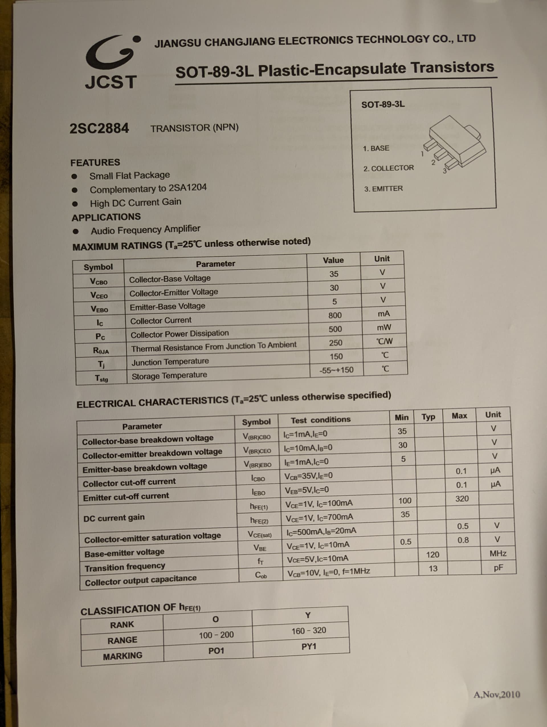
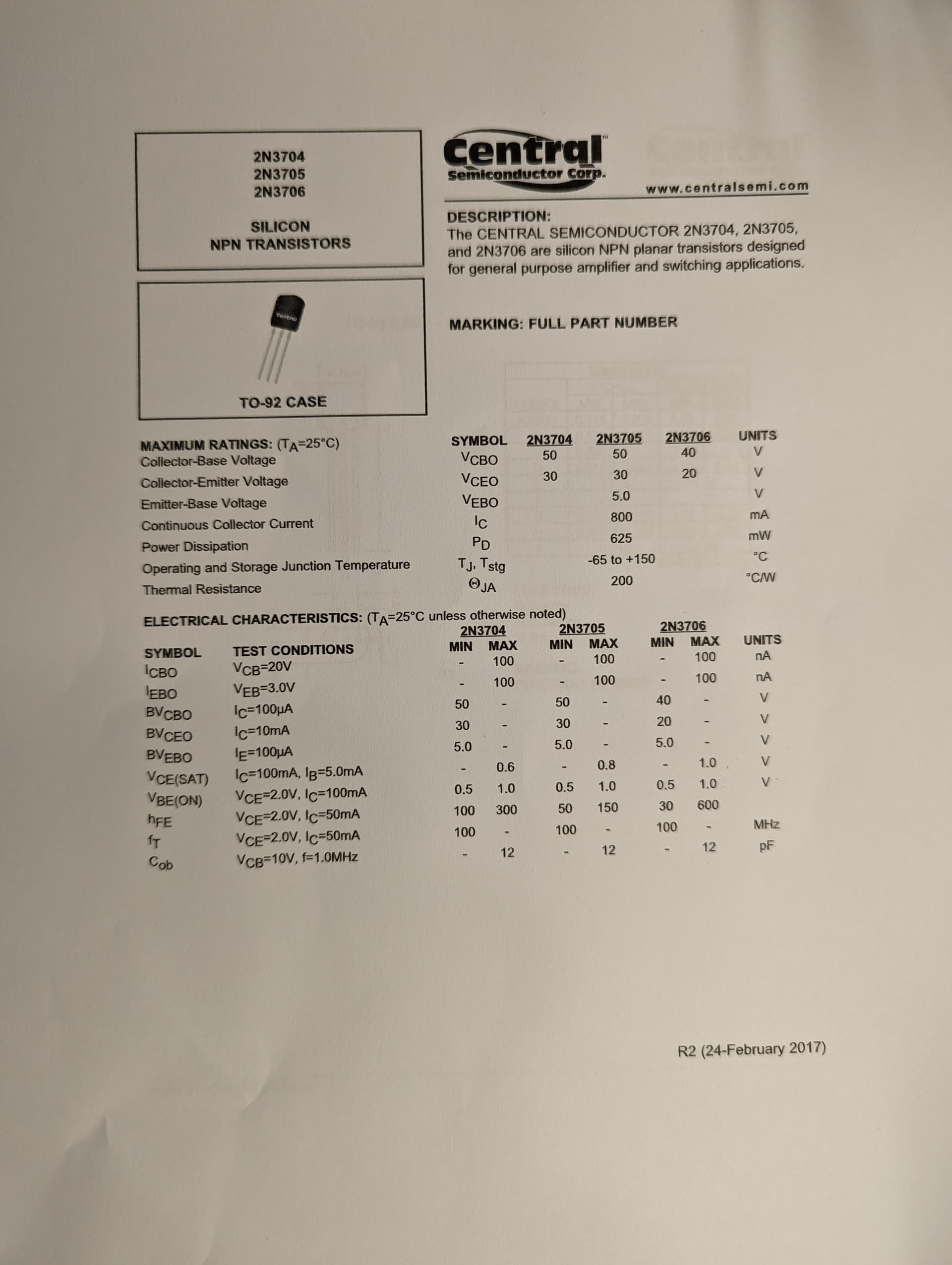
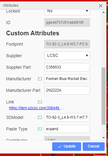
This is the tht equivalent
In easyEDA, if you right click on the green THT part in the trace with the SMD it will give you the part numbers
1 Like
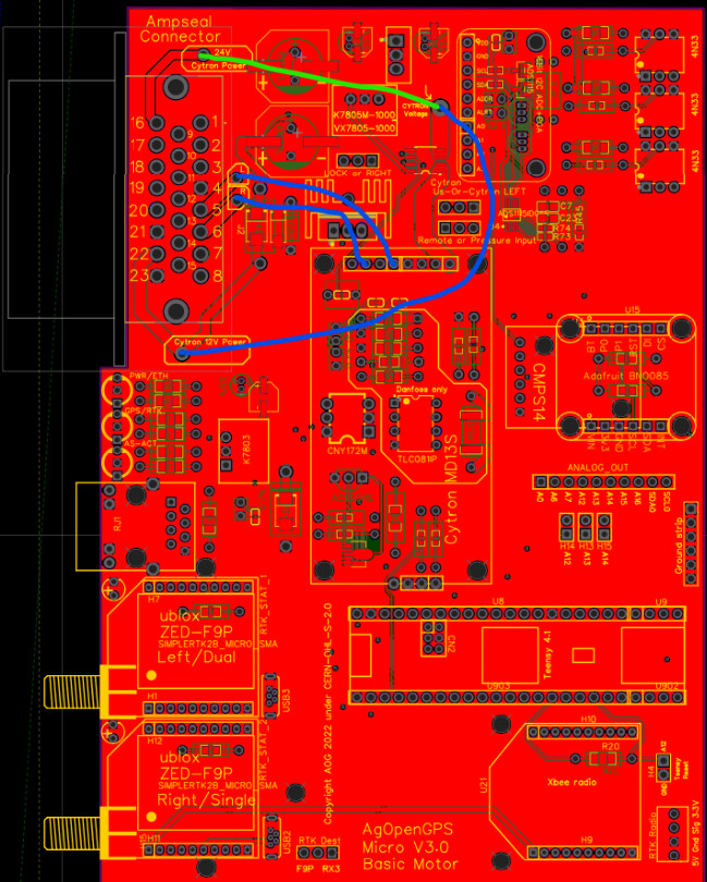
MOTOR Guys
I have edited the Micro PCB and made the traces heavier for the motor guys. Also have removed the CAN bus components and suppressed the Danfoss components, for a more basic all in one for the motors.
It is newly finished and untested, though there are not a lot of changes. To run motors it will need some 16 gauge insulated wires soldered in as jumpers since there is no board space left to get the traces large enough for the higher currents.
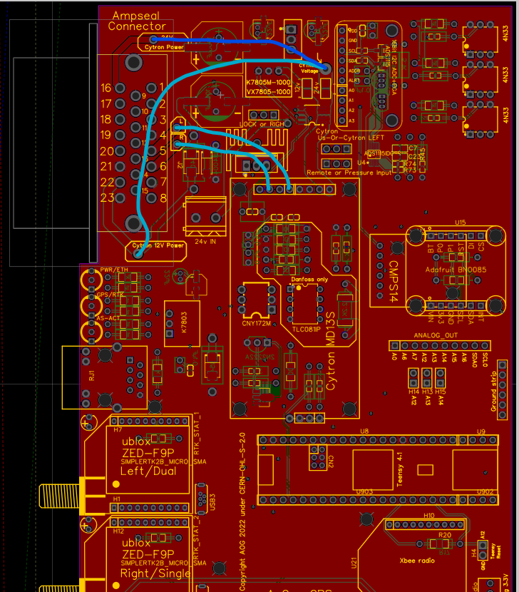
The light blue lines from R/L to the cytron.
The other light blue line is for using 12V in from the board power. If using external 12V or 24V, use the darker blue path and power the cytron at pin 16 of the AMP connector. The 24V jumper will need soldered for all motors and the 12v must be left unsoldered.
https://drive.google.com/drive/folders/1usCFJvlXnaOCqDf0f4bx8o_yOgFUw9XZ?usp=share_link
EDIT
NO more solder jumpers. The google link has been updated
EDIT
Labels on Left/Us and Lock/Right were corrected
Google Drive is updated

2 Likes
I think there’s a slight silkscreen error on the micro board.
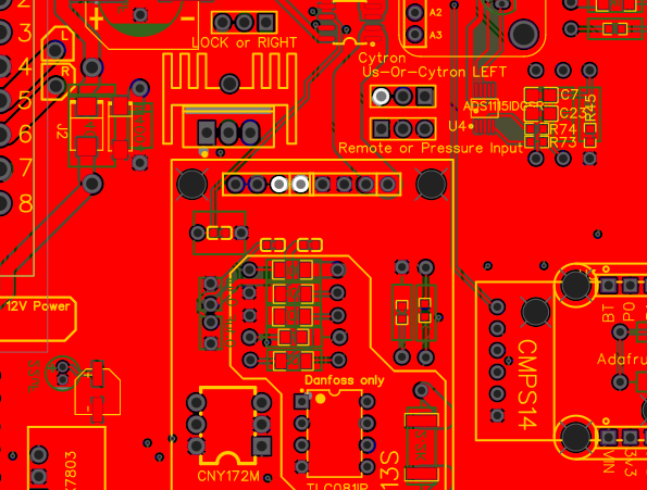
The cytron Us-or-Cytron LEFT should be the other way round, i.e. Cytron LEFT-Or-Us.
It’s correct on the standard board. Same problem with LOCK or RIGHT by the looks of it.
It just means the jumper needs to be the other way round
I changed it and didn’t save it again. I will fix it. Thanks
Edit
Labels Fixed
Correction only for the micros or for the standards?