All in One PCB

Baud rate in u-center?

Yes in U centre.

Can someone explain to me how these work? When I connect these → gnd what happens?
1.WorkPin
2.SteerPin
3.RemotePin

And LOCK, where is it used?

Thank you!

Work pin will turn section control on/off and coverage.
Steer pin turns autosteer on/off.
Remote pin is for a pressure sensor in a hydraulic valve or an encoder on a steering wheel to turn autosteer off if you turn the steering wheel etc.
Lock pin will provide 12V to open an isolation solenoid in a hydraulic steering valve or can be used to control a relay to do similar.

To add to this, I carried out a current test on my AIO with Phidgets 24V powering 3D printed steering cogs on a Claas Arion on a bumpy grass field.

As you can see from the YouTube video below, most of the time the motor is only drawing in the 0.3-0.6A range, you will see in the video I grab the steering wheel the Amps jump up to 3.6 Amps, I was grabing the wheel quite hard, fighting the motor, far in excess of any reistance ever likely to be encountered.
I deliberately started off line at the start, so it had to turn aggresively, you can see it maxes out at 1.35 amps.
On a U-turn, right at the end of one of the videos, it gets upto 1.35 Amps.

I upgraded to a custom multimeter holder in this second video:

So for most of the the time steering on the line the current is in the 0.2-0.6 Amp range, aggresive steering, like on a U-turn got to 1.35 Amps and grabbing the wheel hard got to about 3.6 Amps.

@Jhmach the 1oz traces on the AIO Cytron input/output are good for about 3.5 Amps?

So 24V phidgets is perfectly ok to use through the AIO traces and Ampseal socket.

Would be nice to have a 24V input on the Ampseal socket :stuck_out_tongue:

Consequently, I’ve put a 5 amp fuse on the 12V input to the 12-24V converter (so 2.5 Amps on 24V). And will set the current sensor to disable autosteer above 2 amps approx.

7 Likes

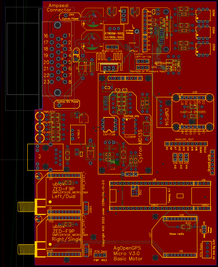
Nice work. This is good news for a lot of motor users. The V3.0 board above has 2mm traces on 3 layers and should handle most motors. It still needs the jumper wires to the pad eyes provided for full amps on big motors.
I deleted the CAN bus from this more basic version and used pin 16 to input 12v or 24v straight to the cyrton. or the 12v board input can still be used for 12v motors.

3 Likes

Does the Deutsch connector work number to number when putting pins in place? Connector numbering seems like it is different to the electronic image but it depends on what angle you look at. So can I just put number 1 pin in number 1 in connector?

Yhteenveto


image

Also second question, it is possible to put on/off switch on this board or do I need to install it on power wire?

Edit: I found the Gerber files and looks like it is indeed number to number.

You can view schematic in EasyEDA, hovering over the pin holes will tell you there function and show there connections on the PCB.

Yes, you need to fit an isolation switch and fuse on the power supply into the board.

Very good. But it would be interesting to keep F9P Standard updated as well. I have more access to the F9P STD than to the micro.

Can we use the all in one with a udp to USB adapter ?
My tablet doesn’t have a udp port

Yes, a USB → Ethernet adapter should work fine.

Yes, gigabit adapter. I have been using one for a long time. Nice part is you dont drop the usb connection when you hit a bump and have to stop and reconnect. If its plugged in and loses connection it connects back on its own. Of course a zip tie eliminates that all together.

image
Added two gaps for AMP connector. Thx to Peter Scherer

New Standard Special with screws (AMP connector)
Standard_Special_AMP_Screws.zip (718,0 KB)

Updated first post about 3Dprint

1 Like

I placed an order at jlcpcb. They sent an email and ask the following:
Imag
Can I confirm that?

Thank you @Jhmach for putting together this design!

Other than the CNY172M it seems to have everyone populated by JLCPCB

(Before you ask I already have place for almost all the boards and didn’t even advertise yet)

1 Like

There was some discussion in Telegram about positioning IMU horizontally.

I have mounted my new PCB vertically and switched the code so it seems like IMU is working correctly on showing the tilt of the tractor. Is there some problem with something else if BNO is not horizontal?

And if so, is there some easy way to change the mounting, I wouldn’t like to use wires and make new mount for it.

Edit: I am testing and now it looks like it doesn’t work vertically. Tilt goes same way either side when twisting the board. Could I use CMPS14 instead or does it have the same problem?

It bothers me that the hands are not taken in one piece. The Teensy was difficult to put on. The distance in a collision is always a little too big. I will solder the Haeder myself next time.

I agree, but for the Teensy I find if you break the headers according to the PCB sockets it works much better.

Did anybody tried out a pure through hole variant already ?

So my plan is to mount BNO on the cover of the box like this:

Then it is horizontal when box itself is vertical. Just a shame to have those annoying extra wires in there since everything else is so nicely mounted on the PCB.

Anyone know if it ok to drill those holes in the corner of the BNO little bigger? At the moment my plastic screws don’t fit them so I’d need to make them bit bigger.