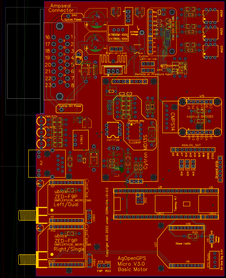
pressure sensor is connected at the 12v input to the cytron. That jumper needs connected as well. Just right of the status LED
So jumpers just between the pins? Connect those 2 pins that are next to each other? Or between those left and right? And how about that pressure pin?
just the middle pin and the one next to it, yes. If you use a pressure sensor then use a jumper on that one as well. Do some checking about the sensor type. I think its 4-20 mA but I have not used that feature. If you don’t use anything to kick the steering out, just leave it un jumper’d.
1 Like
Then there still is question about those 4 connections. Since I would imagine left/right would be 2 valves but there is 4 in the Baraki valve.
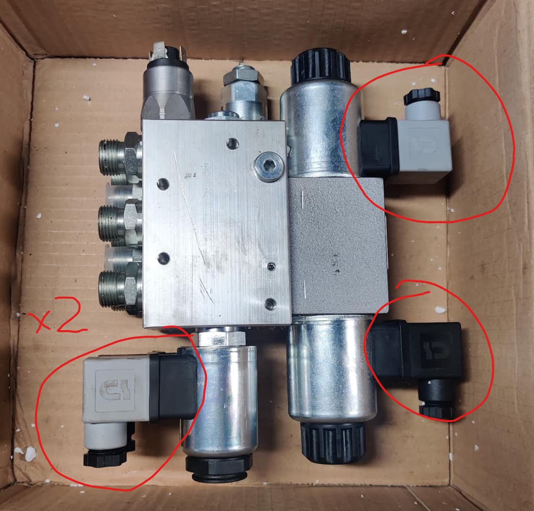
x2 are safety valve , connect together .
1 Like
Baraki valve is pressure switch. Connect as remote.
So safety valve should be connected to pin 8, not 9?
safety valve is pin 6. LOCK is the power pin for hydraulic shutoff solenoid, 9 is steer switch, 8 is if you use that pressure sensor on the top left in the picture. you don’t have to use that sensor to get up and running though.
So does any one have the pinouts for a raven pressure sensor part # 422-0000-086 its a 3 pin plug
appears to be 4-20ma type from what little i can find on them
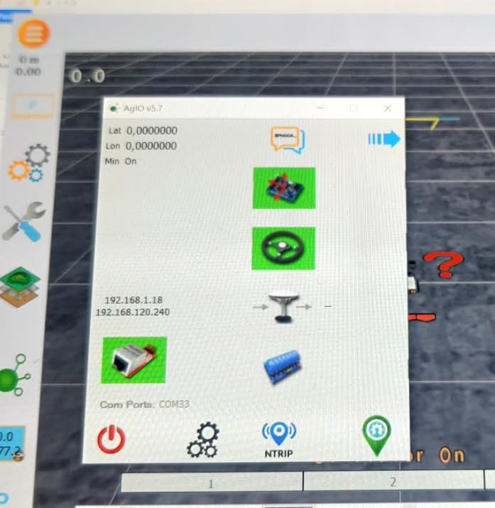
Is this normal with this board when only powering through Teensy? I can’t seem to get any antenna reading and not any data going trough. I flashed new version to Teensy and now tried testing board before connecting to tractor and 12v.
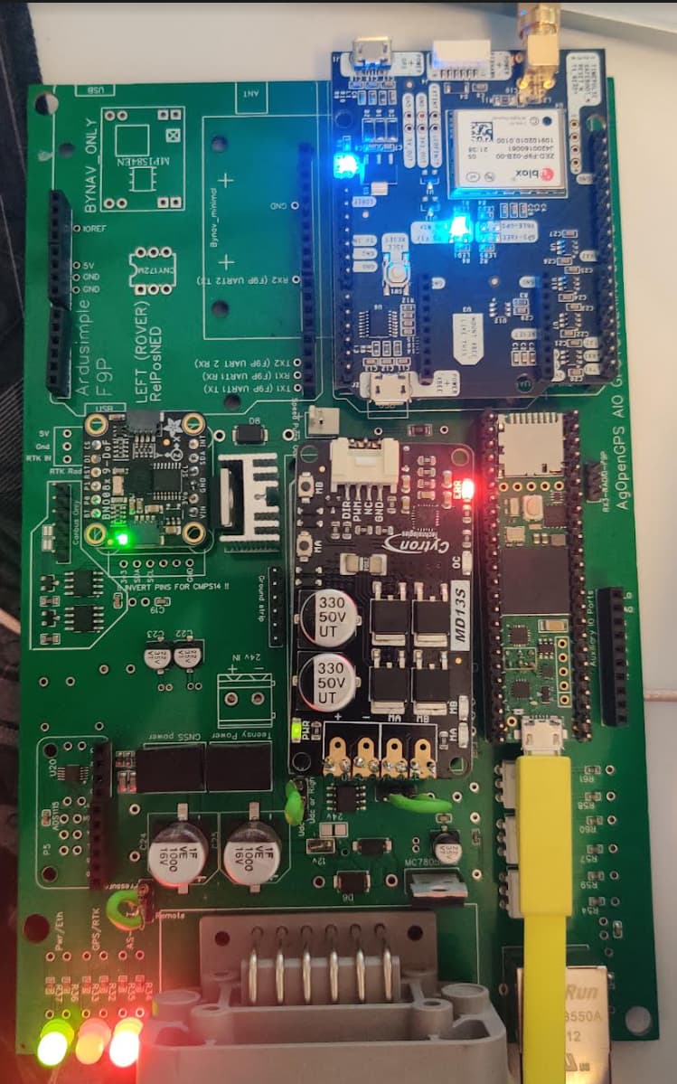
The middle led is off?
Have you updated the firmware and config files on the F9P?
I had this same scenario this morning, updated F9P with latest firmware and config (in the support folder), set the baudrate to 460,800 and the three leds should be on.
Thank you, that solved it! Everything seems to ok for now. Also seems like it would be possible to mount PCB vertically after modifying code
Baud rate in u-center?
Yes in U centre.
Can someone explain to me how these work? When I connect these → gnd what happens?
1.WorkPin
2.SteerPin
3.RemotePin
And LOCK, where is it used?
Thank you!
Work pin will turn section control on/off and coverage.
Steer pin turns autosteer on/off.
Remote pin is for a pressure sensor in a hydraulic valve or an encoder on a steering wheel to turn autosteer off if you turn the steering wheel etc.
Lock pin will provide 12V to open an isolation solenoid in a hydraulic steering valve or can be used to control a relay to do similar.
To add to this, I carried out a current test on my AIO with Phidgets 24V powering 3D printed steering cogs on a Claas Arion on a bumpy grass field.
As you can see from the YouTube video below, most of the time the motor is only drawing in the 0.3-0.6A range, you will see in the video I grab the steering wheel the Amps jump up to 3.6 Amps, I was grabing the wheel quite hard, fighting the motor, far in excess of any reistance ever likely to be encountered.
I deliberately started off line at the start, so it had to turn aggresively, you can see it maxes out at 1.35 amps.
On a U-turn, right at the end of one of the videos, it gets upto 1.35 Amps.

I upgraded to a custom multimeter holder in this second video:

So for most of the the time steering on the line the current is in the 0.2-0.6 Amp range, aggresive steering, like on a U-turn got to 1.35 Amps and grabbing the wheel hard got to about 3.6 Amps.
@Jhmach the 1oz traces on the AIO Cytron input/output are good for about 3.5 Amps?
So 24V phidgets is perfectly ok to use through the AIO traces and Ampseal socket.
Would be nice to have a 24V input on the Ampseal socket ![]()
Consequently, I’ve put a 5 amp fuse on the 12V input to the 12-24V converter (so 2.5 Amps on 24V). And will set the current sensor to disable autosteer above 2 amps approx.
7 Likes
Nice work. This is good news for a lot of motor users. The V3.0 board above has 2mm traces on 3 layers and should handle most motors. It still needs the jumper wires to the pad eyes provided for full amps on big motors.
I deleted the CAN bus from this more basic version and used pin 16 to input 12v or 24v straight to the cyrton. or the 12v board input can still be used for 12v motors.
3 Likes
Does the Deutsch connector work number to number when putting pins in place? Connector numbering seems like it is different to the electronic image but it depends on what angle you look at. So can I just put number 1 pin in number 1 in connector?


Also second question, it is possible to put on/off switch on this board or do I need to install it on power wire?
Edit: I found the Gerber files and looks like it is indeed number to number.
You can view schematic in EasyEDA, hovering over the pin holes will tell you there function and show there connections on the PCB.
Yes, you need to fit an isolation switch and fuse on the power supply into the board.