ADS1115 should be SMD so you don’t need to add another.
CMPS14 is an alternative to BNO085 they are IMUs or inclinometer. You only need one of them, most popular is the BNO085.
You need to buy one and solder header pins and mount on the PCB. JLCPCB do ot stock these ever.
U16 and U17 on the Standard board are chips for CanBus, you don’t need them if not using Canbus.
1 Like
The ADS 1115 wasn’t included to my JLCPCB.
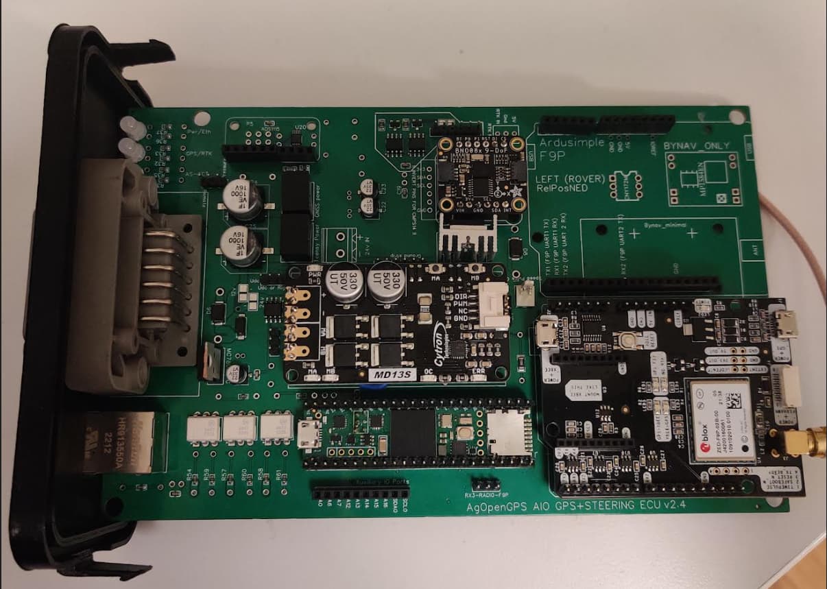
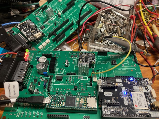
Here is my board:
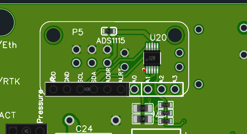
Do I need a chip only or a board with chip?
Like this?
The link has everything selected in the BOM for a basic board to use the cytron to run motor or standard valve
https://drive.google.com/drive/folders/1zrq5fCmgnHIgDfPKuzCoCPbCredL4bm6?usp=share_link
All of the description is above
1 Like
U20 is the smd ADS!!
Thank you so much!
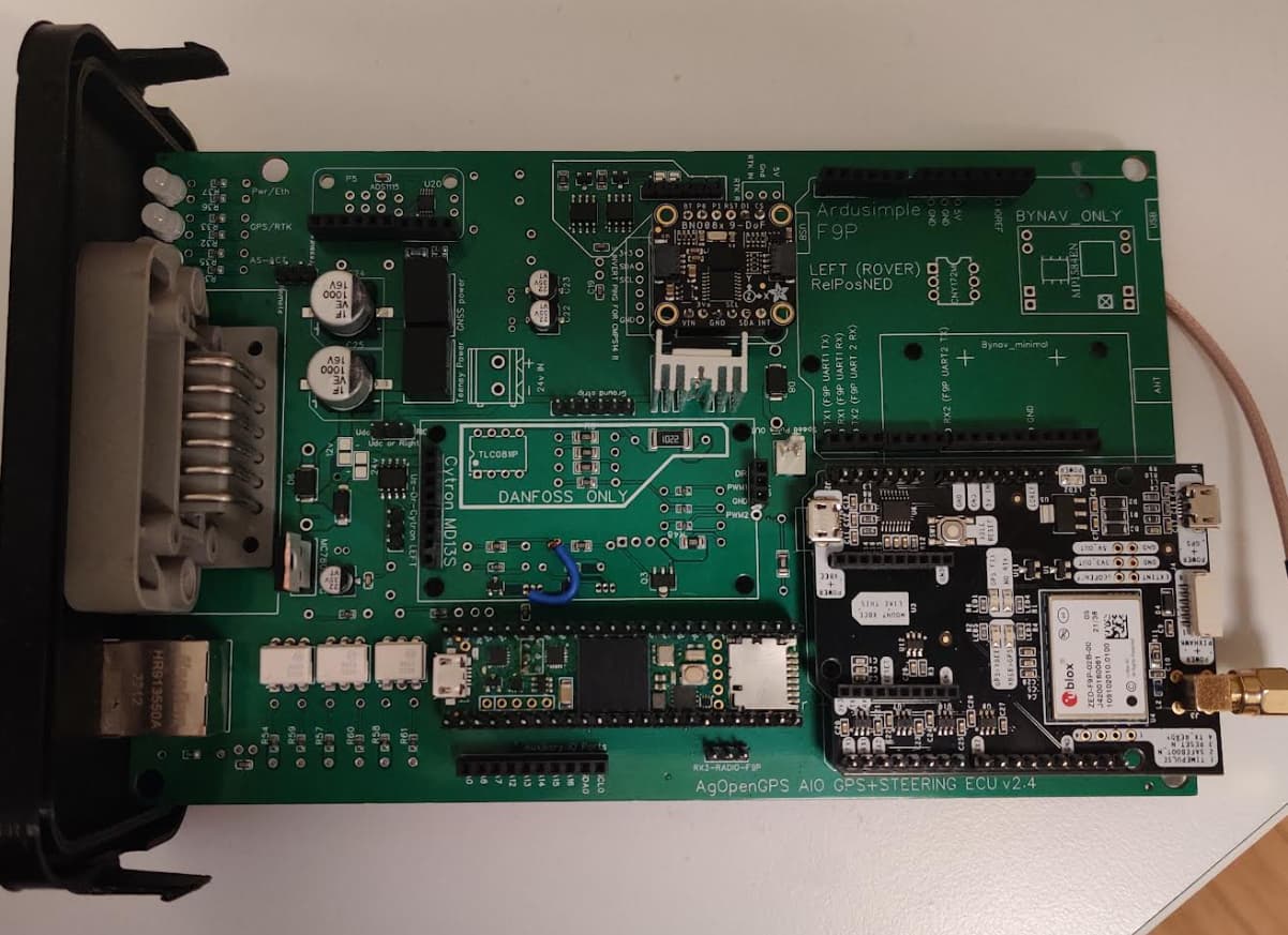
So i have all in one board V2.5 i got everything working but the steering
i’m running a danfoss valve is the plan
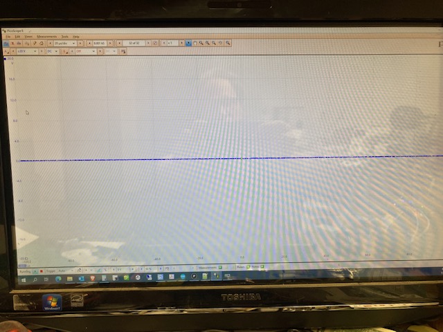
i have it on the test bench i’ve got a scope hooked to PWM pin for the cytron
the jumpers are set per the pdf that come with Agopen
i have teensy Autosteer_gps_teensy_V5_5 loaded
i can see my angle sensor read was runnig through the setup wizard and got to the point to see if the steering is correct and i’m not getting any signal on the AMP plug pin 5 with scope
so i followed it back before the TLC081 and checked still nothing check at pin 4 teensy and nothing there so not getting PWM from the teensy
made sure i have the jumper right and in the software i have the danfoss valve selected
Is there anything else on has to do to get and output ?
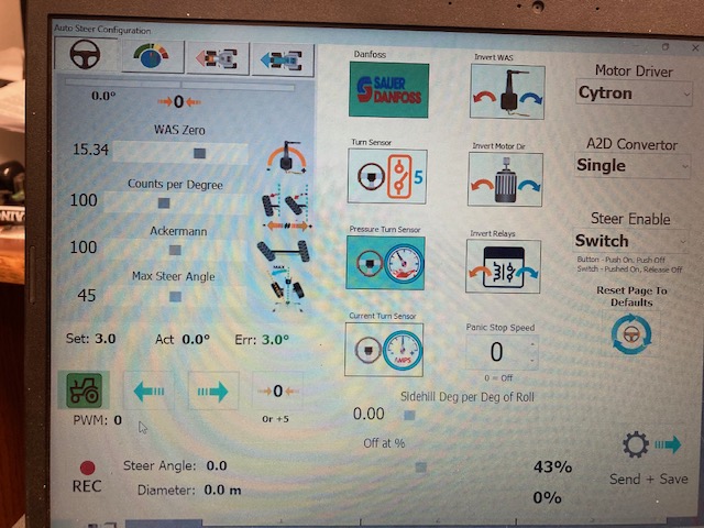
Nothing i do sets a PWM signal on the pin or on this screen is there something that i’m missing
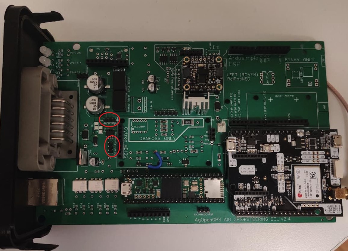
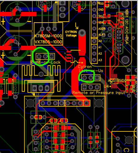
I’m not sure if it was fixed on the board you have but the silkscreen for the jumper was wrong. Jumper should be between the center pin and the pin with the square pad (right side).
silkscreen says Us-Or-Cytron LEFT
but the pinout is actually Cytron LEFT-Or-Us
Yes i checked that and it’s correct
also used a ohm meter to verify that it goes back the R46
You arent getting pwm on the drive screen, so ita not sending it from aog to the board. Is the steering wheel green from the autosteer switch being engaged ?
Only the micro incorrect. Standard is fine.
Didn’t realize when you ran the wizard and got to that point you had to press the steering switch to check the direction of the steering
Thanks that got me a reading
I guess some folks already have those modules (as they are pretty expensive) and if we put everything to a board we can say goodbye to repairability (should we ever need that)
Hello everyone,
Just a quick question, which config file to use for F9p if using single micro one? There is the single rover and there is the dual position in the boards folder in GitHub.
Then the single rover for the tractor (rover).
I am finally starting to install my new PCB. Can anyone say how to wire Baraki hydraulic valve with Deutsch connector? There is 4 different electric valves + pressure sensor.
Also I am now installing manual button for autosteering, do I wire that on pin 8 and ground?
And final thing, is it ok to mount PCB vertically, arrow pointing down? I have BNO085, before with Kaupoimod I used CMPS14 like this without problems.
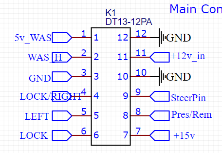
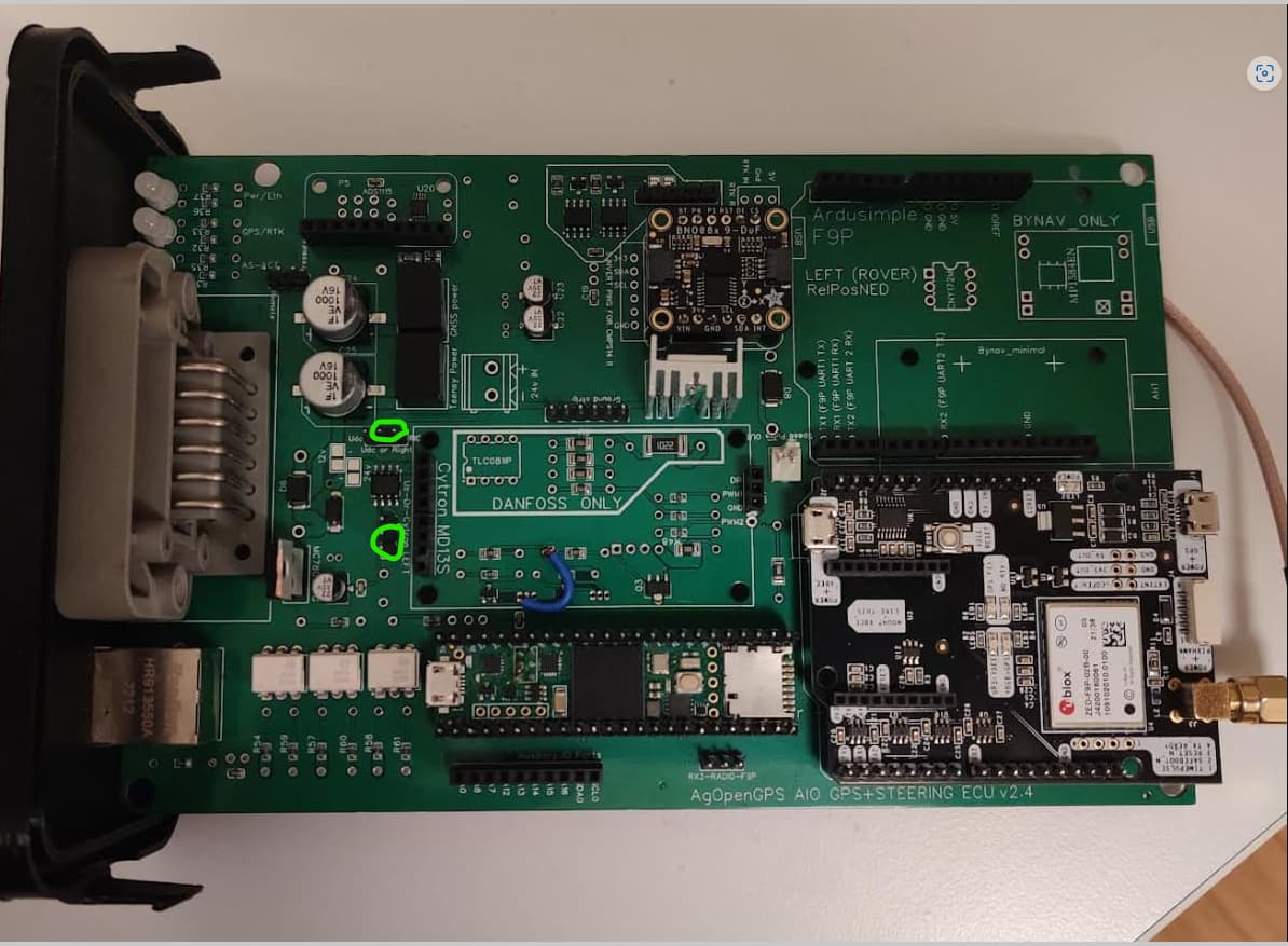
use oin 4 right and pin 5 left for the Baraki valve. Make sure you put the jumpers on and remember they are labeled incorrectly before January 6.
Use lock pin 6 for the safety valve. It engages with the steer switch.
Steer pin 9 and ground for steer switch.
I couldn’t say on the bn0 working on it’s side, maybe test it and see. If that is the only way you have to mount the box, I would suggest a 90 header to get it level.
Thank you, thats helpfull. What do you mean with the jumpers, there is different layout on my board compared to your picture. I have made that one jumper under Cytron, I guess it was causing problem with WAS?