20 is the “+15v” marking which corresponds to the +12v output of the pcb protected against phase inversion by the diodes.
22 is +12v in which powers the PCB from the tractor battery.
20 is the “+15v” marking which corresponds to the +12v output of the pcb protected against phase inversion by the diodes.
22 is +12v in which powers the PCB from the tractor battery.
Thank you
The 770680-3 has 6 contacts blanked off, you do not want this one, you need 770680-1.
And 776087-1.
I used the same CNY172M, I believe its correct.
great, thank you .
and concerning the contacts, it is the reference 770520-1 that is needed.?
out of curiosity where did you see for the 6 contacts blanked off.?
Yes 770520-1 looks correct, I ordered 770854-1 cannot see much difference other than one is max 1.3mm and the latter 1.5mm.
If you look at the attached PDF you will see the contacts that are blanked off:
ENG_CD_2293782_E.pdf (357.9 KB)
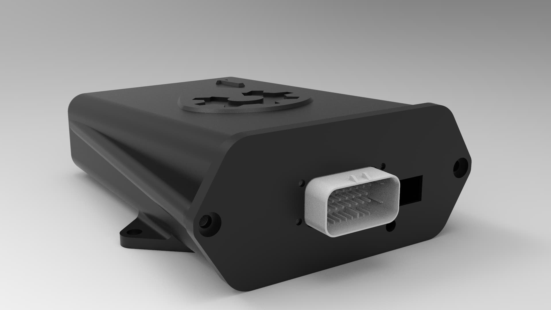
If you look closely at the pcb I see 3 LEDs which are soldered but none that come out in the case smce it is a shame to mount LEDs which give information but that it is not visible from the outside
proposes the use of led holders for the front of the housing
Question again ![]()
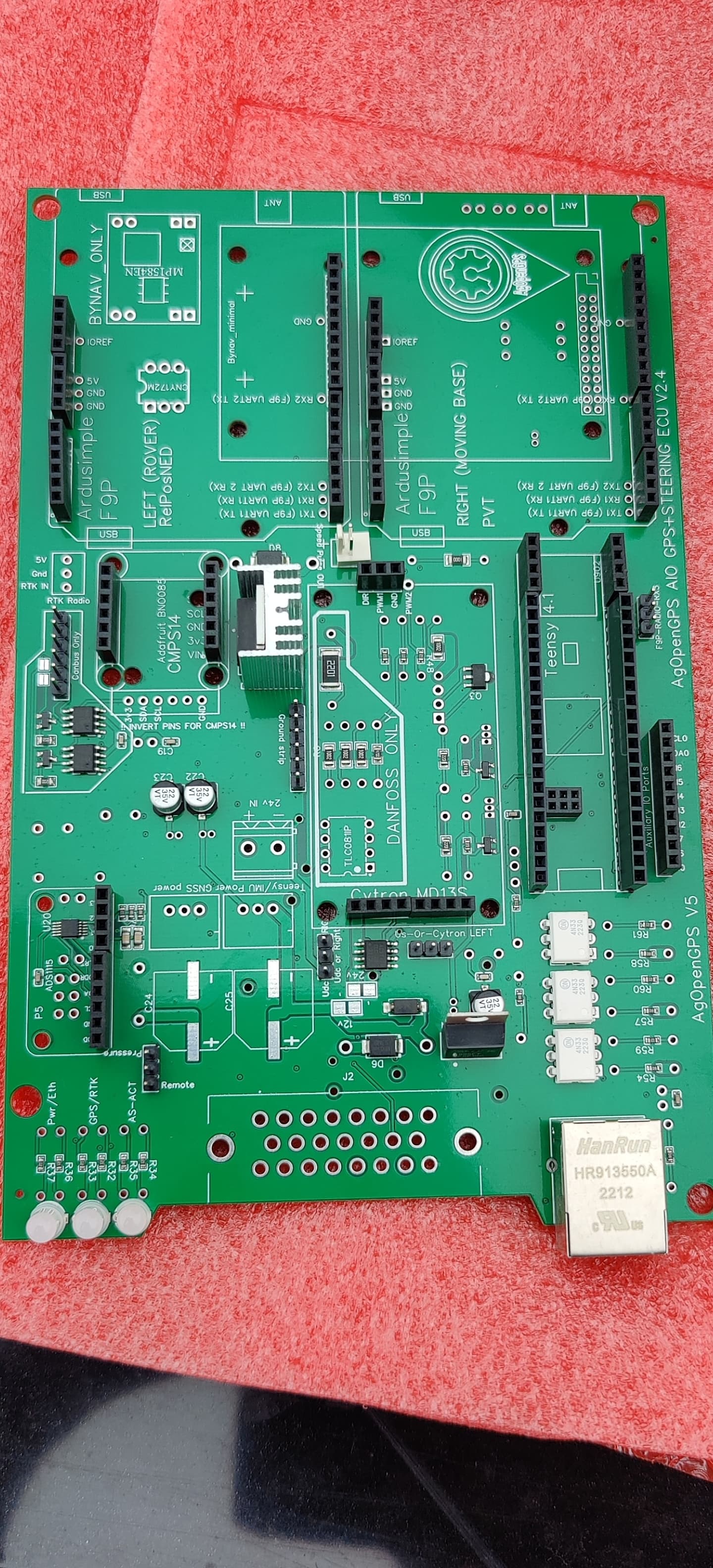
Steerpin, how to connect? On old board you had two connectors.
You connect to GND somewhere.
Best is the same GND spot as the AIO board ![]()
So steerpin switch/button to gnd
Does the IMU need to be mounted in a correct direction, like 0 degrees? If so, could it be smart to have a bracket that the box attaches to? That way it’s easy to remove it if necessary, and get it back in exactly as it was before, even without tools… Just a thought!
I think the design looks good ![]()
The IMU needs to be mounted with one axis parallel to the tractor’s front-back direction (as indicated by the arrow on the box) in order to determine roll properly. It also has to be mounted flat in order to determine heading properly. This is in the order of +/- few degrees I’d say; not in the decimal order.
I like the idea of a bracket for the box since on the cable side it’s already easy to connect/disconnect the box with Ampseal/Deutsch connectors.
Well, when I have mounted IMU’s onboard vessels we had to be within 0,1 degrees(calibrated in SW), but there was also longer “arms”. Not only the deviation. ![]() By having 3 screw points, it would be easy to level a bracket. and then it’s possible to connect/reconnet the box and get the exact same position for the IMU every time
By having 3 screw points, it would be easy to level a bracket. and then it’s possible to connect/reconnet the box and get the exact same position for the IMU every time ![]()
Is vibrations or heat an issue?
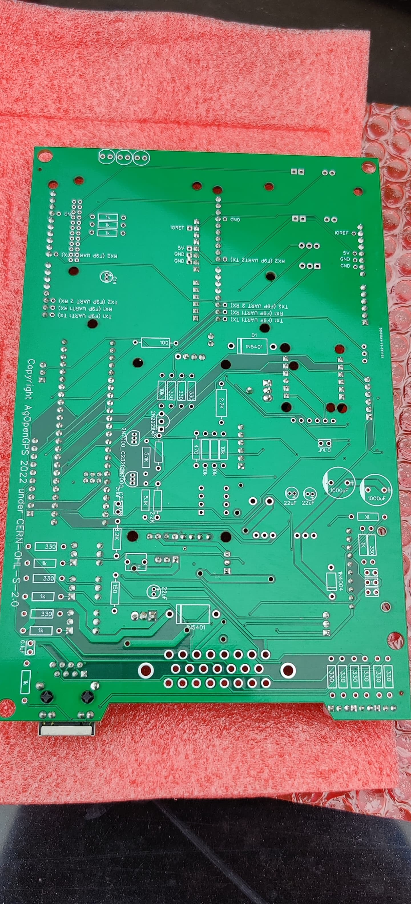
i have received my order. A couple of smd capacitors are missing from the top. Can I replace this by soldering condenser at the bottom of the page?
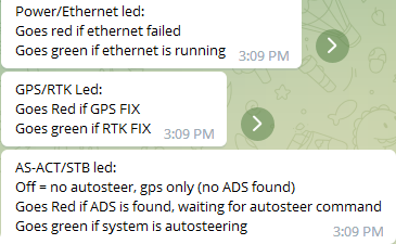
Here is the description of the 3 LEDs on the board
Use the 1000uF that are used on the original V2 board. Place them on the top, not the bottom
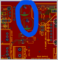
is this a substitute for the capacitors of c24, c24 smd?
C24, c25
The position that Jhmach circled are the through hole options for C24, C25. They are marked on the bottom but you should put them in through the top.