I’m powering the cytron directly TeddyStamford said I don’t need them
So you are - ignore that then ![]()
I will try it tomorrow
Who here has a all in one with 2 f9p because mine keap messing around
The LED light for the gps doesn’t turn on but I’m still getting rtk
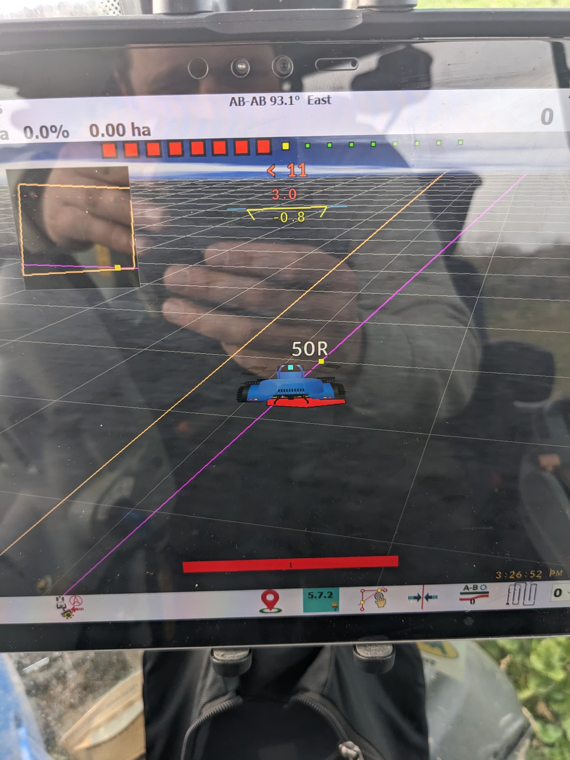
When I plug it in I’m going backwards on the map and the ampseal connector is facing the back of the tractor
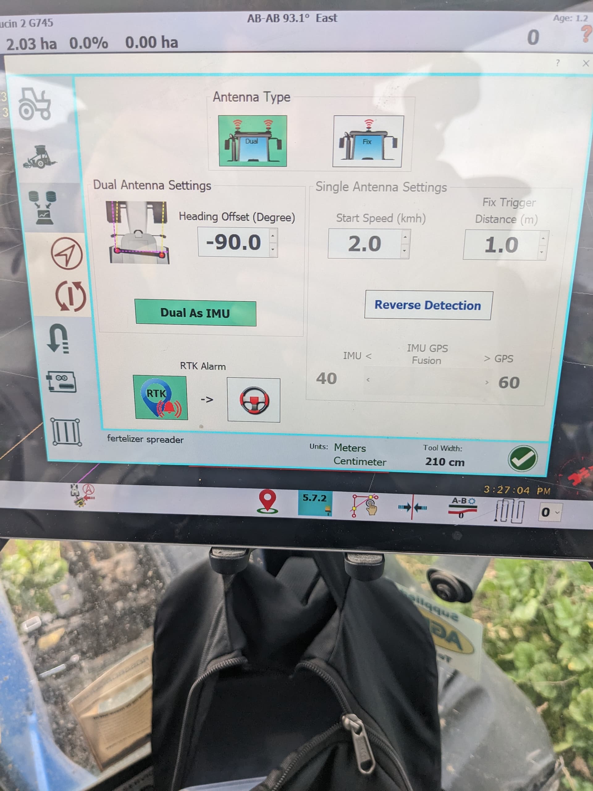
The tractor keeps going in a angle I have changed the angle to -70 so the tractor looks inline withe the ab line but after a few minutes past it goes off again and I need to go and change the angle again and my antennas are at maximum 3 degrees out
So it might be the f9p config?
I upload it from the support folder
Or the teensy ?
With a resistor between signal and GND to create a 0-5V signal ?
A 250ohm resistor added between input and ground will give you a 1-5v signal. Not familiar with what you are trying to accomplish. You may need to scale accordingly in sketch.
Remove the IMU from the board and make sure your antennas have good view of the sky.
The heading offset should be 0 in AgOpen
Don’t select dual as IMU
Hi, do I need CMPS14 if I have BNO085?
No bno is better then cmps
2 Likes
I think the AiO was designed for 20mA sensor. It needs modifying for 0-5V sensors
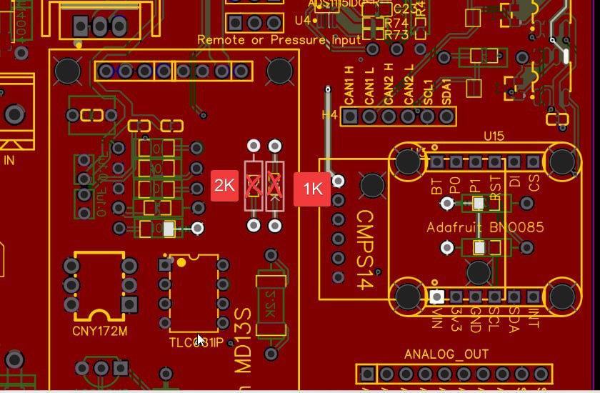
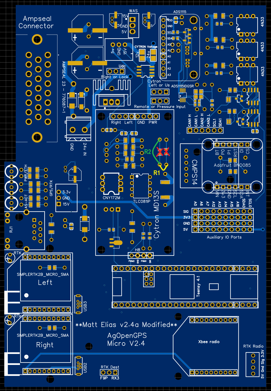
I think so but they need to go in slightly different? For the standard PCB it’s these two as marked.
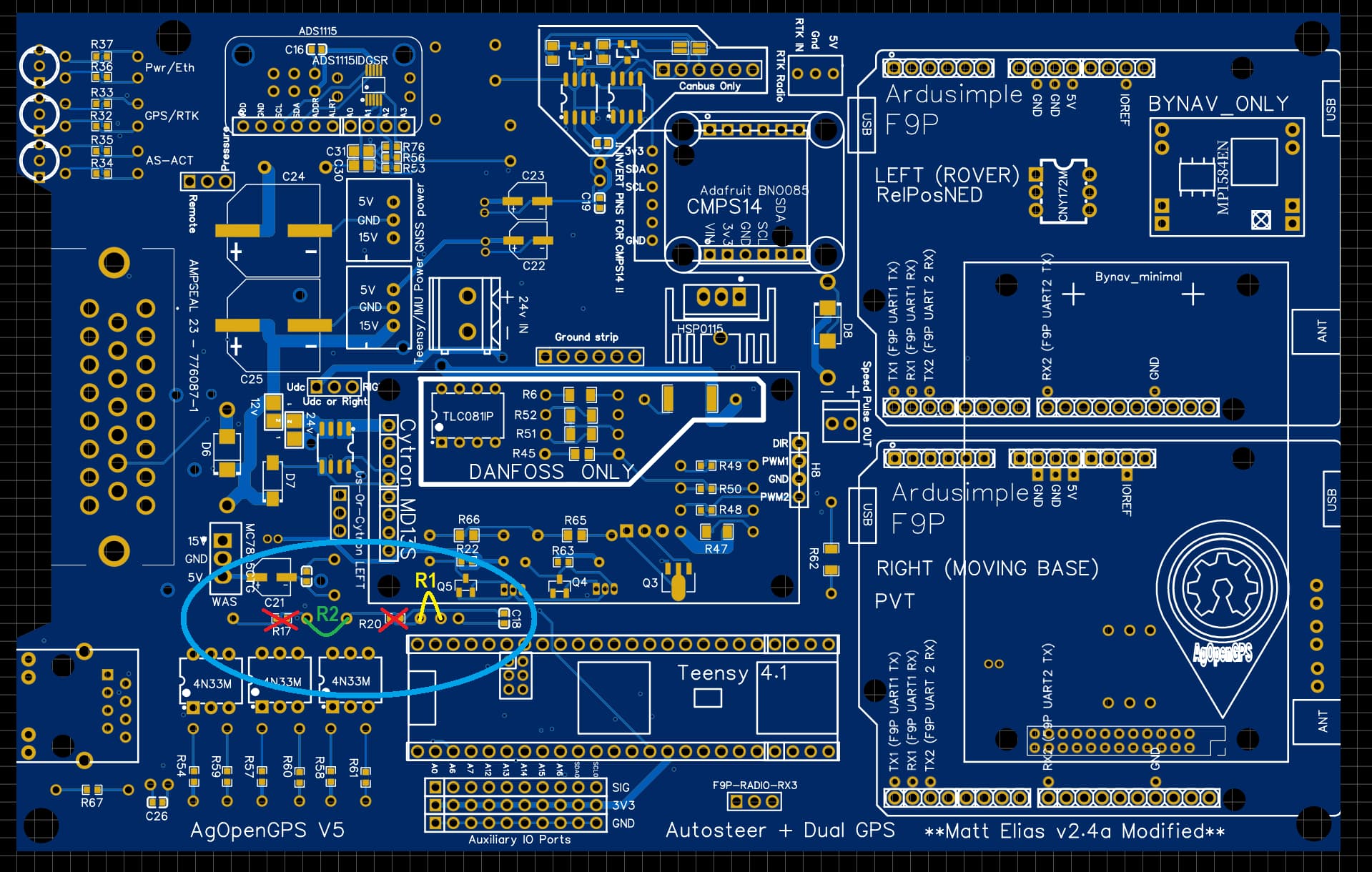
For 0-5V input, use a 1:2 ratio (eg, R1 3k, R2 6k or 5k to be safe)
For 0-12V input, use a 3:1 ratio (eg, R1 6k, R2 2k)
1 Like
For 0-5V input, use a 1:2 ratio (eg, R1 3k, R2 6k or 5k to be safe)
For 0-12V input, use a 3:1 ratio (eg, R1 6k, R2 2k)
For the standard ampseal Aio where are board checks to be performed before mounting Teensy or micros? On the standard board prior to Jan 6 are the Left and Right jumper pins labeled correctly?
Thanks
I think that only shows it for the micros. Wondering if there would be something similar for the standard ampseal aio
I had done basic testing on your two PCBs. And the Right/Left labels are correct on my modified PCB.
Hello. Tell me what could be. Tested today micro with IMU. When driving north, it rides fine. When I go back, there is no straightness to the south. And sometimes jumps to the side. Again I’m going north, everything is fine. I’m going back, there is no straightness and sometimes jumps to the side. Version 5.7.2. The base is about 30 km away.
Creating the AIO pcb was a great job! Maybe it is becoming THE hardware.
Maybe I can express a wish for the next version:
I am using an DELL Venue 11 Pro 7140 as tablet pc which requires 19.4 V for charging. Currently I am using a Bootst DC/DC converter module which converts the 12 V battery voltage to the 19.4 V. There are several potential modules available
(e.g. Amazon.de or even smaller)
The output voltage is usally adjustable by a potentiometer, so all common tablets can be powered.
Perfect output connector would be a specially marked (red) USB Port, since it is quite dangerouse since it is delivering 19.4 V instead of 5 V.
Than the table is powering on and charing automatically as soon as the AIO Hardware is switched on.
I think it is worth thinking about defing an optional place on the PCB for such a module to make the system more and more smarter.
Perhapps it can be comined with the 12 to 24 V stepup - converter for the motor. (Boost from 12 V to 24V + Buck from 24V to 19.4 V)
Would love to include the tablet power, but putting a large regulator coil in with the “delicate” components is a bad idea. I have my regulator tucked away in the cab and powered from the same switch as my AIO board, it works well.
2 Likes