Yes, double checked… Even tried switching it to some lower (both in code and in u-center) and returning it back after…
Don’t think baud rate is problem because it’s working on 5.6.1 and both ino files expect same baud rate…
Yes, double checked… Even tried switching it to some lower (both in code and in u-center) and returning it back after…
Don’t think baud rate is problem because it’s working on 5.6.1 and both ino files expect same baud rate…
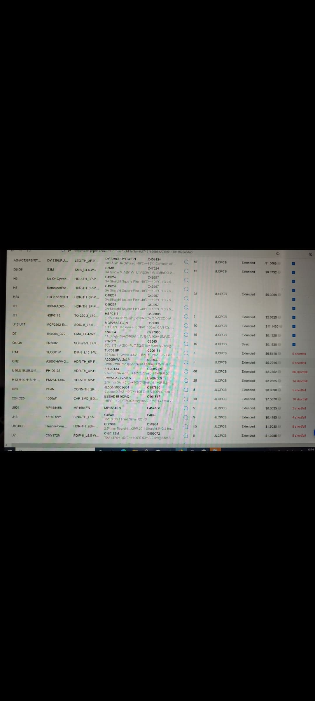
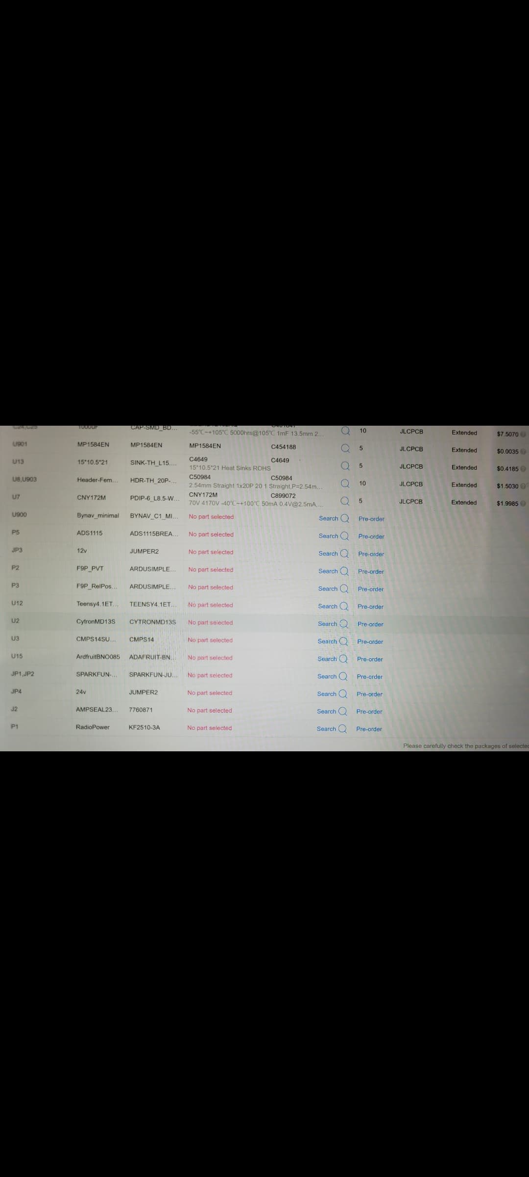
Hello, I am working on ordering my first pcb and want to make sure its right before I place the order. Is that amount of unavailable parts acceptable? Do i need to find them and solder them in myself?
I guess its not that many, what does the shortfall mean?
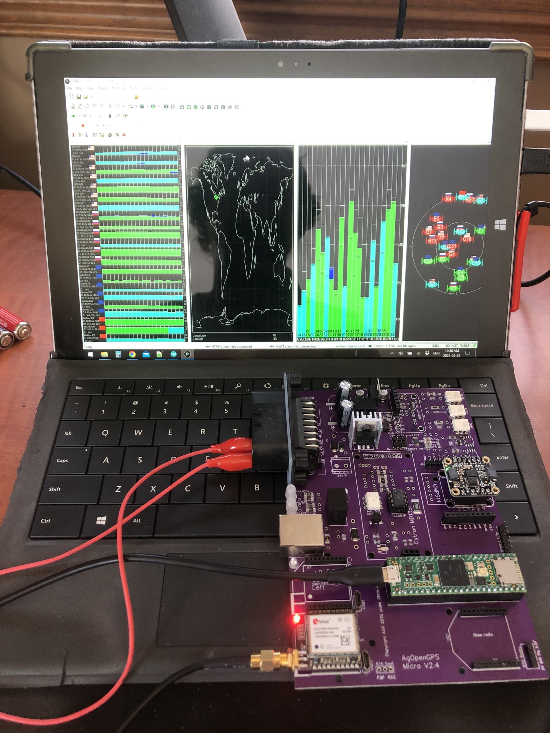
Hmm it was laying on a rag when I was testing…
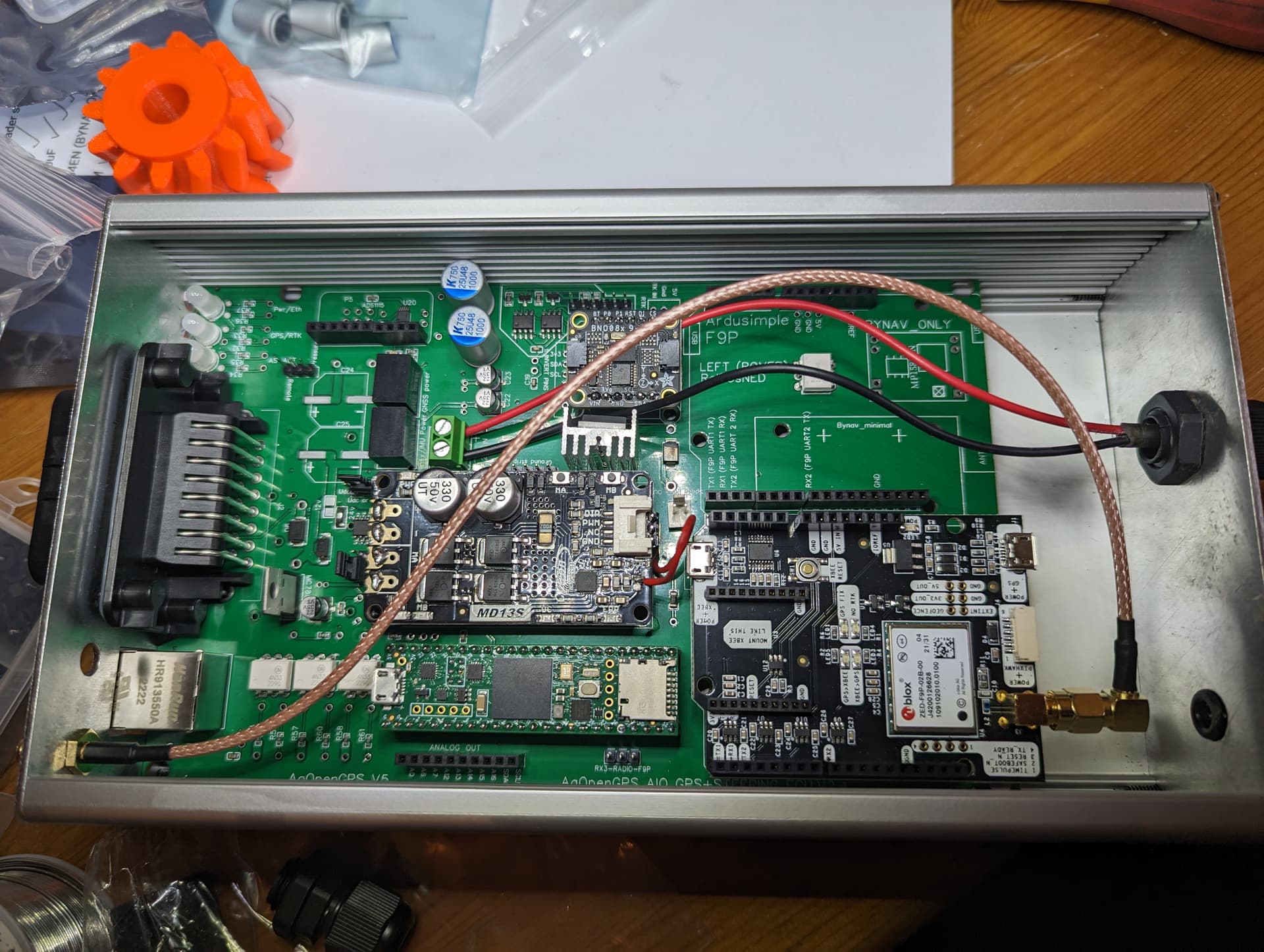
I know some have complained about poor soldering of the micro F9P USB ports on the AIO Micro boards and have had to carefully swap boards around to get their Micro F9P programmed. I wanted to share this workaround that I found.
You’ll need to power the AIO board with 12v and you’ll need a Teensy. You should cut the power trace on the bottom of the Teensy because you will be connecting USB to the Teensy while the board is powered by external 5v. Described here: electrical testing and validation · farmerbriantee/AgOpenGPS_Boards Wiki · GitHub
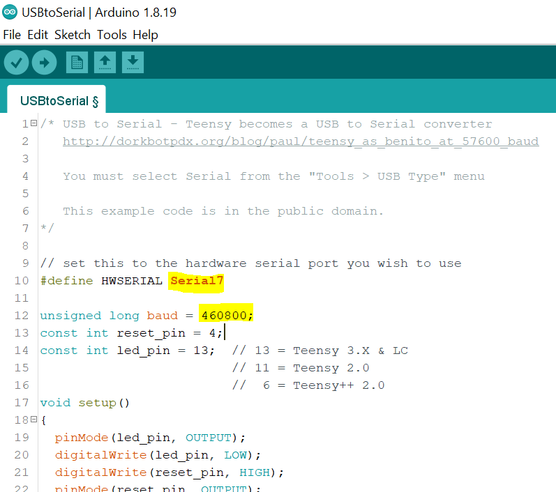
The Teensy can be used as a virtual serial port. You can think of it as a USB-Serial adapter. It just takes a little bit of code, which is already in the arduino IDE examples folder File->Examples->Teensy->USB_Serial->USBtoSerial
Upload the code to the Teensy. When complete you can use the COM port and baud rate in U-Center to connect to the Micro F9P. U-Center seems to not always recognize COM ports added after U-Center was opened, so make sure to boot the AIO board before opening U-Center. From there you can view connections, flash firmware, etc.
When finished with the boards you will want to upload the Autosteer_gps_teensy_vX.X ino file to the Teensy to use AgOpenGPS.
I hope that can help someone in the future.
Could someone confirm the action / purpose of the “pressure / remote” jumper on the AIO PCB?
It selects whether the Remote input pin is processed as a encoder/interrupt or 20mA analog pressure sensor, for disengaging autosteer.
I did a shopping cart for the Ampseal23 and other miscelleanous items:
https://www.aliexpress.com/p/wishlist/shareReflux.html?groupId=fczLSHlxISW4kwot6iUp%2Bubg08OVwqAbFOAwpawaACE%3D
(also on the wiki: connectors · farmerbriantee/AgOpenGPS_Boards Wiki · GitHub )
You’ll also need:
WAS cable: 7meters of 3x0.5mm2 wire it’s likely more than enough. I’ll try to get this more precise as I build them. (I only found 4x0.5mm2) YSLY-JZ (árnyékolatlan vezérlő ) 4x0,5 mm2 (1x100fm rendelés esetén) szürke sodrott réz PV
Power input: 7 meters of 2x0.75mm2 wire (I only found 3x0.75mm2) YSLY-JZ (árnyékolatlan vezérlő ) 3x0,75 mm2 (1x100fm rendelés esetén) szürke sodrott réz P
However the switch requires 3 wires so this is perfect for the switch, the input will have an extra cable and the motor as well unused…
(links are in Hungarian, hopefully give you an idea what to search for)
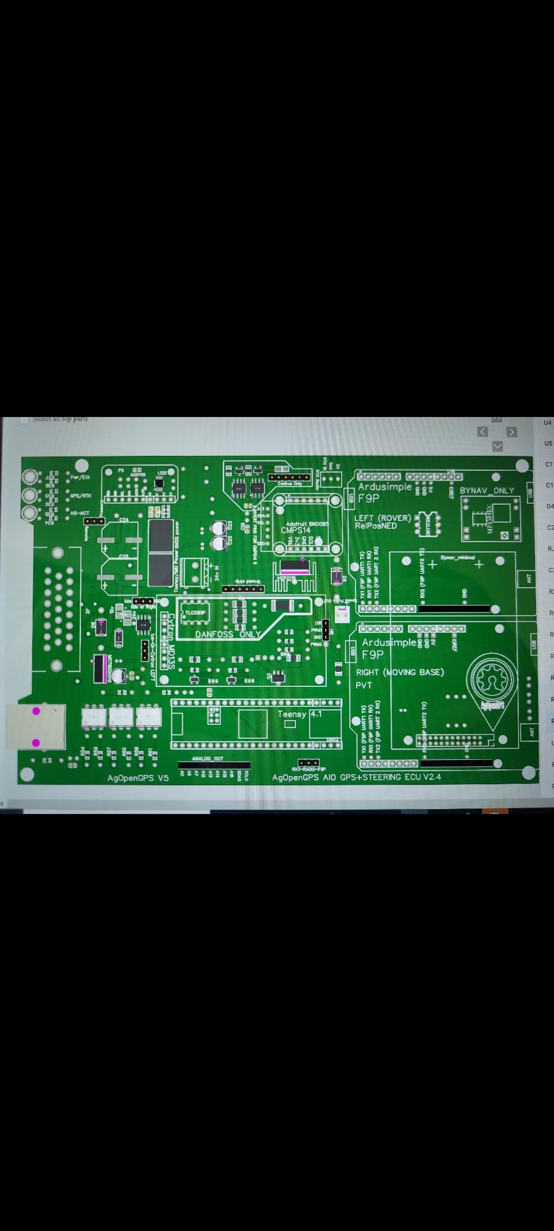
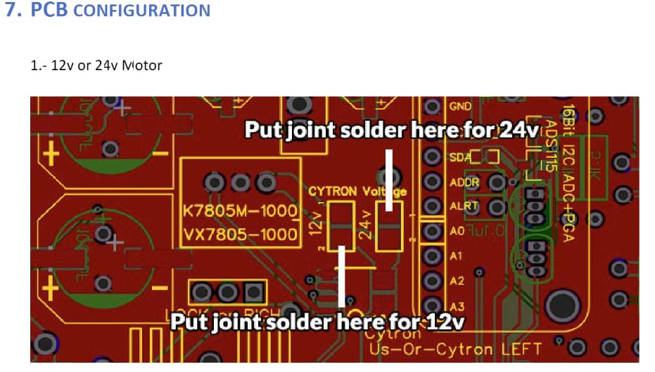
Can someone explain what “Put joint solder here for 24V” means in picture attached? I will be using 24V motor with modified Cytron. Do I still have to use the 12v to 24V converter or does the board have the 24V necessary? I am trying to keep up on everything but sometimes it gets confusing.
Yes you will still need 12 to 24V converter.
You need to make solder bridge between the 24V pads.
You will then input 24V to the PCB into a nearby screw terminal.
You can see 24V screw terminal with the red and black cable connected.
If I have this correct, you have your 12V to 24V converter outside the box, 24V is coming in through red and black wire, then the 24V goes through cytron and out to motor through pins on ampseal plug? The bridge is just a solder connection of the two square pads in yelllow box marked 24V.
After failing to get my center LED to come on after repeated Teensy uploads and F9P firmware/config redo’s, I tried editting the Teensy ino LED code to:
Status LED’s
#define GGAReceivedLED 13 //Teensy onboard LED
#define Power_on_LED 9 //Red
#define Ethernet_Active_LED 10 //Green
#define GPSRED_LED 5 //Red (Flashing = NO IMU or Dual, ON = GPS fix with IMU)
#define GPSGREEN_LED 6 //Green (Flashing = Dual bad, ON = Dual good)
#define AUTOSTEER_STANDBY_LED 11 //Red
#define AUTOSTEER_ACTIVE_LED 12 //Green
uint32_t gpsReadyTime = 0; //Used for GGA timeout
I swapped the 5 and 9 and the 6 and 10.
Now I’m getting the left light as Red (GPS fix with IMU), the center light as Green (Ethernet Active), and the right light as Red (Autosteer is not connected).
When I unplug the ethernet cable, my center light turns off rather than going Red. I think it should stay as Red if the board is still powered up. Does this mean that my center LED might just be damaged and unable to turn Red?
Am I interpretting the code and lights correctly? I’ve never programmed before so I might not understand what I’m seeing or what I did.
hi guys today i encounter a problem my surface pro 4 keep disconnecting the wifi as soon I plug the all in one board this has never happen before and been using it for a week or so
I think the pc expects the internet by udp
The wifi only works when I unplug the udp does anyone know how to fix this ?
Set that registry key to 2 (edit: sorry, should be 0)
Still doesn’t work ,
Think it’s supposed to be a zero, my fault
It could also be an issue with your computer.
For example my Lenovo has a BIOS settings that disable WiFi when ethernet cable is connected.
This should be a part of the “configure tablet” in wiki.
It’s weir some times work other doesn’t but I run it for more than a week and never had a problem
I had this issue. It was a windows issue, prioritising Ethernet over wifi even when there is no internet on the Ethernet. Somewhere on here is how I sorted it out.
[edit…]
Here.