For the MFA motor users (french guys!)
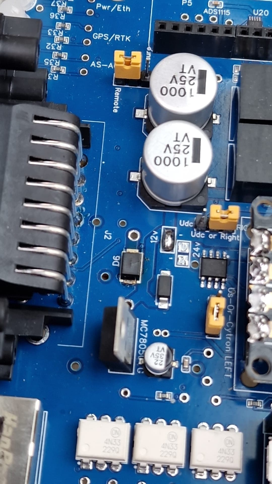
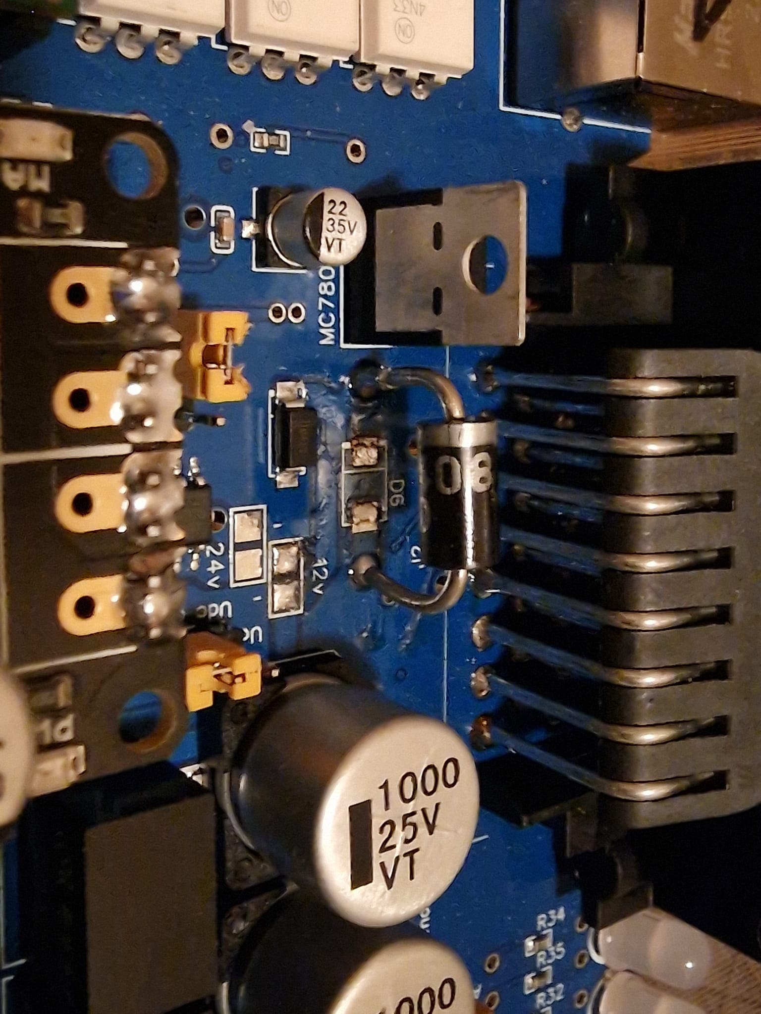
The motor driver can take too much power and it can fry the D6 diode.
I include some pictures how it looked and how we fixed it.
D6 is slightly different color (and has 5V on the other side)
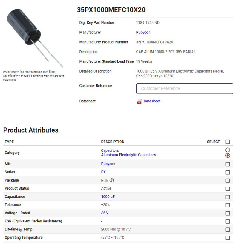
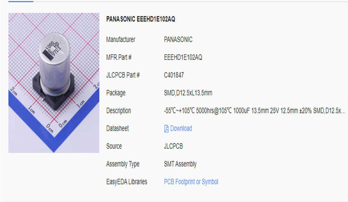
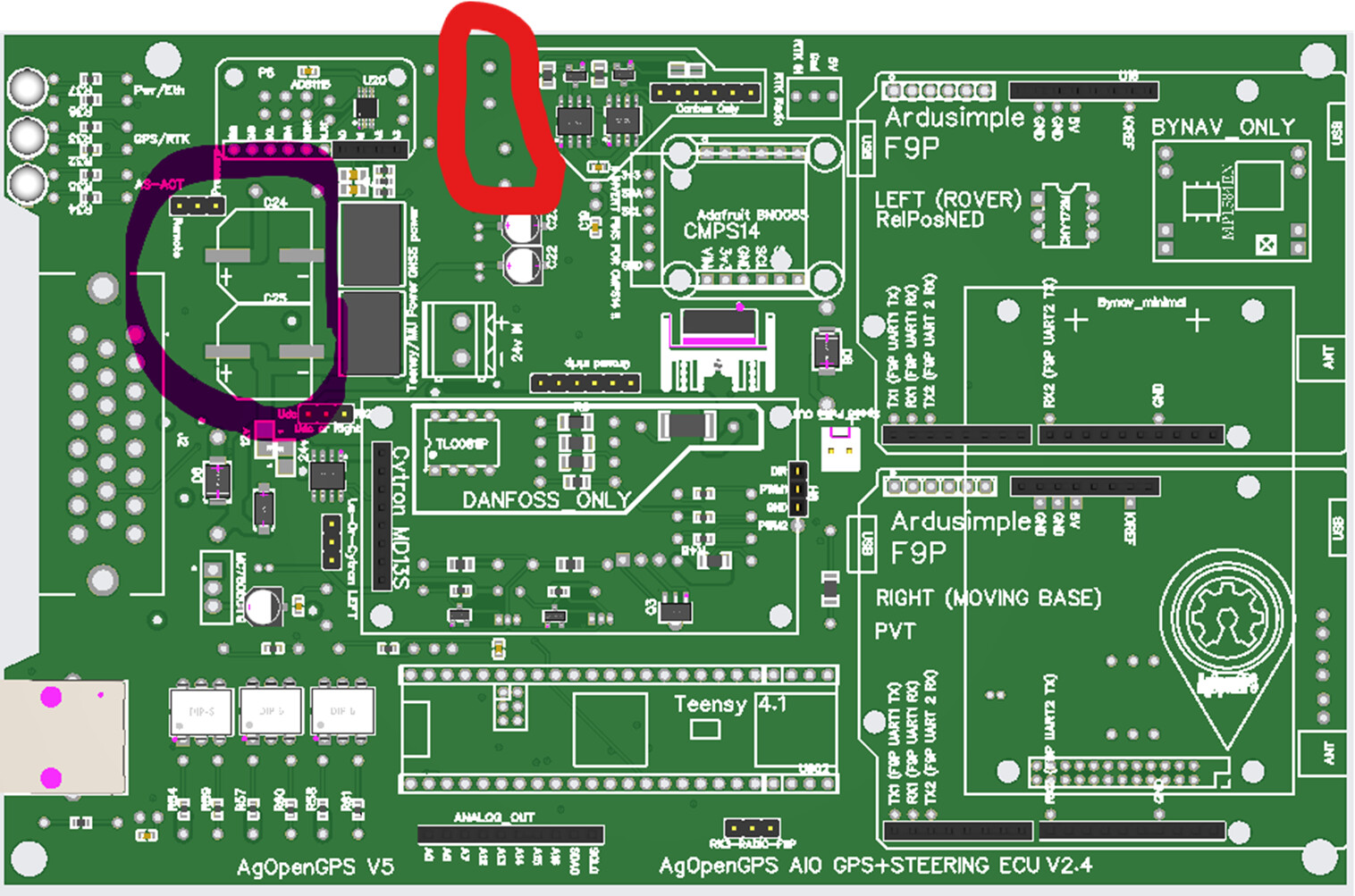
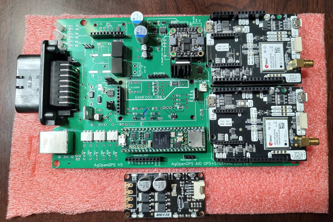
I am getting ready to order the all in one board and would like to clarify something. JLCPCB still does not have the component for c24, c25, thought I read on hear that I can use the 1000uf’s that were used on V2. Can someone confirm this?
Also does the through hole components go in the holes circled in red below?, based on the information on back of board is where I am getting my assumption. Thanks for all your help.
Because vertical GPS accuracy is only half of horizontal, you are going to see see minor jumps in the roll, even when standing still but it should be okay. AOG does some filtering on the roll.
As I stated earlier I am getting ready to purchase the all in one board, I just read on telegram that there may be some more changes coming to this board due to the hard to get components. Should I wait a little longer before ordering or is the basic board not changing just the components? thanks for any updates.
yes I have seen the substitute list, I was just trying to confirm that the board it self was not going to be changing. Do not want to order and a week later there is a change to the board. Thanks
This board has been replaced and updated. Check out “all in one pcb”
We are close to the next release as well.
I can send a new link to this one if its what you want though
So what code should i be using in the all in one board
My tractor WAS sensor is on the canbus Kubota M201 i got the wiring information from the dealer and it show the WAS connector under the cab and its gnd can high and can low wire in the plug so i need to read the canbus to get my steer angle sensor
I’ve created the cable to plug into this plug and connect it to can1 on the all in one board
i tried to upload the Autosteer_AOGv5_Teensy4.1UDP_SteerReadyCAN but that doesn’t seem to work with the board i get no lights but it does find the BN008
Is there a version that to be used with this board?
Another first time build here. I’ve followed AgOpenGPS on and off for about a year now and decided to pull the trigger and start building. So far I’ve ordered Dual GPS V5_v2.4 Std AMP boards that I pulled from repo GitHub - farmerbriantee/AgOpenGPS_Boards: Hardware PCB and firmware for AgOpenGPS Software on Feb 26th. I’ve got my first board nearly complete and have a few questions.
A little on my setup:
I’m planning to run this on a CaseIH 7220 2wd that primarily runs a sprayer and grain drill. It will also run a corn planter and do occasional tillage. We typically drill and plant at the same time so once I have one tractor up and going I’ll start into the second one (CaseIH 8910). I’m planning to run the Phidget 3269_3 24v steer motor on the first one. Eventually I’d like to get the baraki valve and go hydraulic.
Anyways I’m to the point of mounting the Cytron to the board and digging through discourse it sounds like there has been some evolution in this area since these boards were designed (looks like I should’ve grabbed files from the google link or waited a little longer). Based on the board I have, tractor and motor combination, what board/Cytron modifications should I consider? I’ve seen the board traces bypassed, but saw a recent posted that that may not be necessary with the motor I’m running and I’ve seen the Cytron freewheel mode done multiple different ways. Currently I’m planning to solder an 8 pin header on the one end of the board. On the other I would like to use the cable that came with the Cytron and solder the other end of the cable to the board. Use standoffs to support that end of the board. Should I just remove the 3pin hearder from the board and connect there or is there another spot? Then planning to remove the two components off the Cytron and add the jumper from NC. So basically following the Kaupoi v4.1, just on the AIO board.
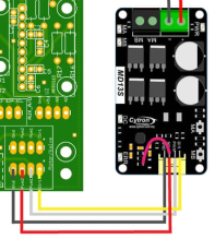
Looks good so far, yes you can unsolder the three pin header at one end of the cytron and solder four wires that come with the Cytron in its place, careful with the order its not in the same order as the cable.
You could just solder three pins to the end of the Cytron, looks tricky but its not to bad and then solder a wire from the hole for PWM2 next to the three headers onto the Cytron.
If using a 24V motor you do not need to bypass the Cytron traces, the Phidgets 24V will only draw circa 0.6 amps in normal use and 1.7 amps on a U turn. The boards current sensor can be used to disconnect the autosteer when you grab the steering wheel, this also has the effect of limiting the current that can pass through the board.
On the board where it says 24V in, you need to solder either a screw terminal or wires directly to the board and bring the 24V in from your step up converter.