@Jhmach are the jumper cables I’ve marked with the red arrows only needed for very heavy motors, the traces from the Cytron are already upgraded to 2oz not 1oz like the Standard AIO?
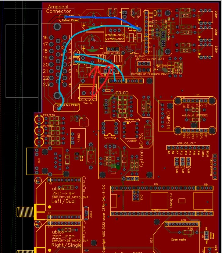
What is pin 20 on Ampseal connector being used for, I see it is 12V out from board but what is its purpose? Is anything connected to it?
I would because the traces are only 1.5mm and what does it hurt?
Not knowing what the motor current is, it’s better to be safe.
1 Like
Pin 20 was for 12v out, but I changed it to power the cytron. You can use the jumper wire and pin 20 to use 24v, but also 12v if you want. Then your cytron is on a separate power source.
The aio board will work with Autosteer_AOGv5_Teensy4.1UDP_SteerReadyCAN ?
Try this, @Arek84 :
I haven’t verified it with the last few commits from origin, at least it’ll point you in the right direction if you do need to change anything.
That’s only for the Micro V3 board?
Think @OhioFarmer64 may be building a standard AIO.
If I understand, 24v can be brought in through pin 20, then a jumper wire is used to get the 24 v to Cytron. Then the Cytron sends the power out to motor through pins 5&6. Would the jumper look like the picture @TeddyStamford post above except use pin 20 & 21 for ground? Yes using standard not micro
On the standard or the micro release board then pinn 20 is 12v out for power to external sensor.
Dont power the tablet with this port.
just a little confused here. so we are back to pin 20 being a 12v out from board pin with no designated purpose. To get 24V to Cytron I will need to bring in a separate wire not through the Ampseal connector? and the 24V to motor will go through pins 5 & 6 of the Ampseal connector?
Yes that’s all correct.
@Jhmach was referring to the Micro V3 PCB which has heavier traces and Canbus and Danfoss deleted, so it can handle high current motors.
If you’re using the 24V Phidgets then the standard AIO’s are perfectly fine running these.
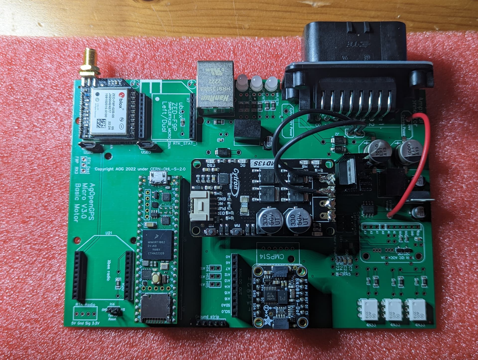
@Jhmach thank you for doing the V3 board, nice to have everything on the Ampseal ![]()
![]()
1 Like
I have modified my Cytron for the free wheel as shown in picture.
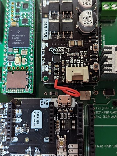
Do I also have to modify the pcb board by removing the resistor circled in red as shown in picture below? Using standard AIO. Also any tips on what type of connecter I can use for the wire going to the PCB hole PWM2 so it can be disconnected easily instead of soldering it. Is there any chance the connector that comes with Cyrton can be plugged in with the three soldered pins there and then just solder the NC wire to the PWM2 hole? that is with the modified wire being connected to the NC wire not the PWM2 hole, and not connecting the other three wires to anything? Thanks.
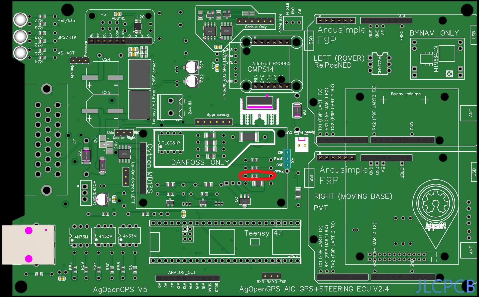
No you don’t have to modify the PCB, only the early PCBs needed that.
Yes you could use the QWIC connector that come with Cytron, cut off the three unused wires and just use NC, and solder other end of wire to PWM2 hole on the PCB.
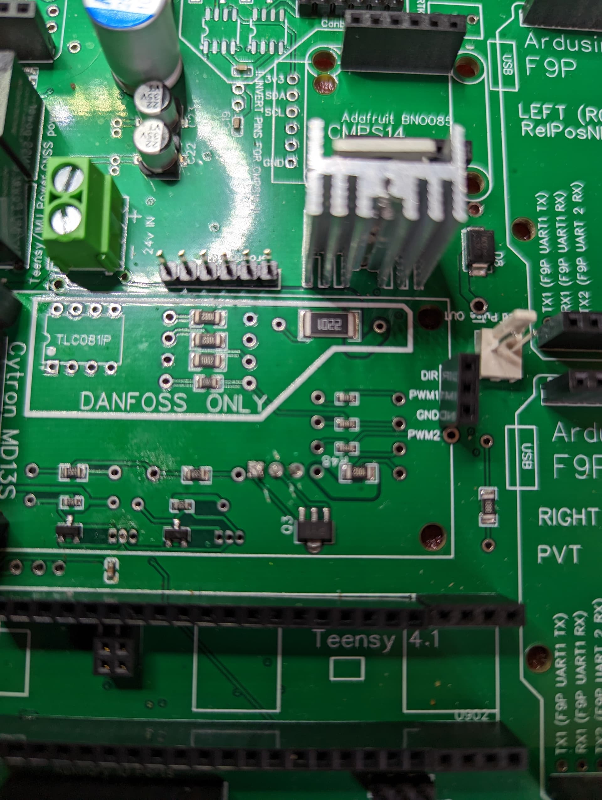
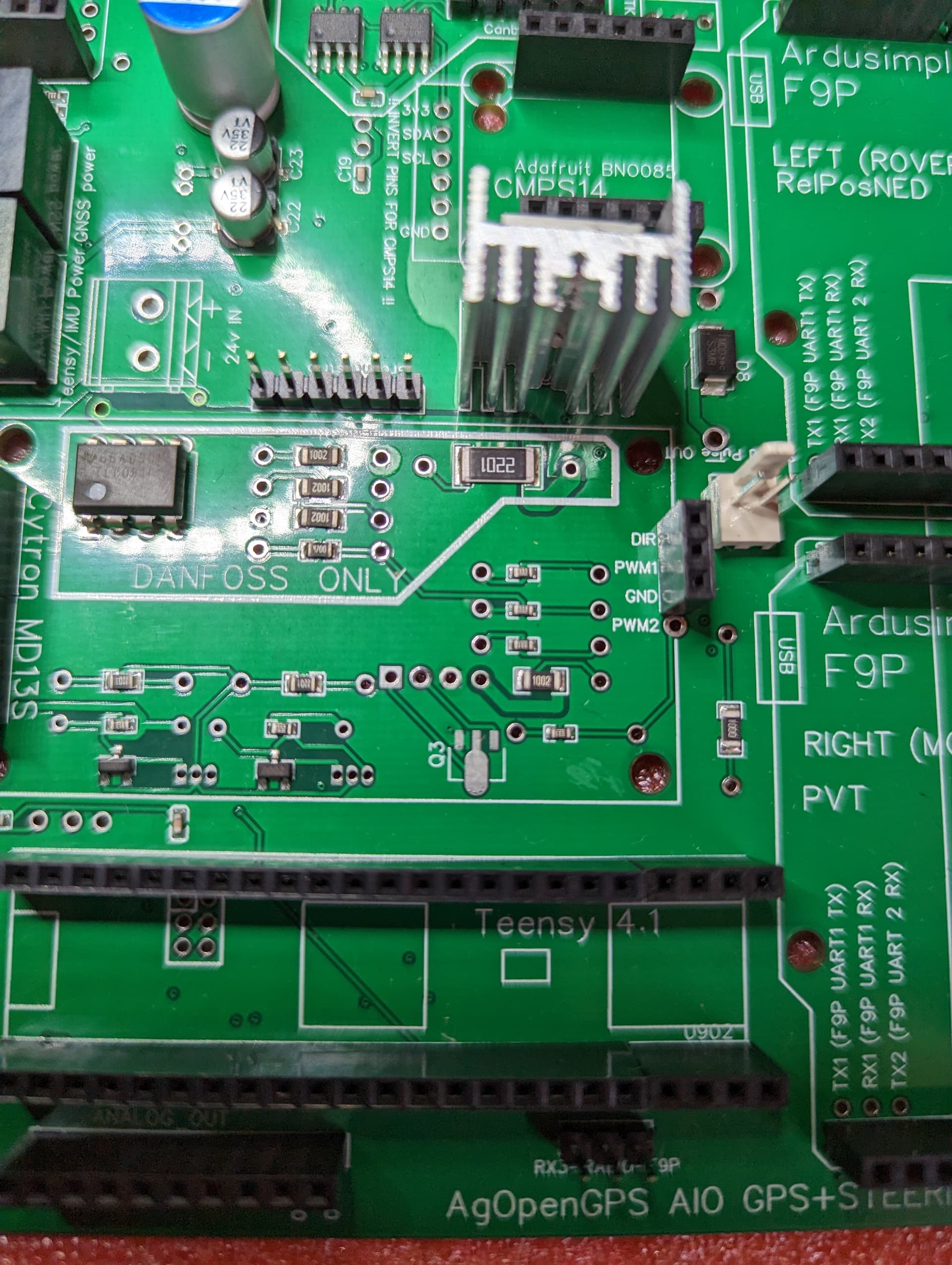
PWM2 trace in picture above needs the fix, the one in the picture below is a later PCB with the fix:
Is the bottom PCB available in Gerber file. I just down loaded the board two days ago and I am not see the bottom board in the file available?
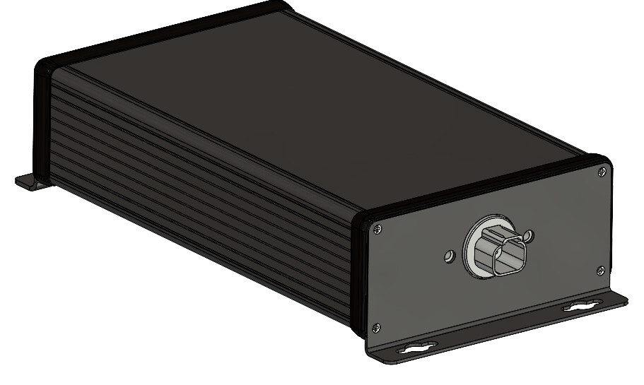
Working on wrapping up my Cytron and faceplate. any reason not to bend up pin 3 & 7 to bring 24v in on. I plan on this board being used with a 24v Phidget and a 3 wire 5v WAS. I have seen some conflicting info on whether I want pin 2 or 3 for WAS signal (wiki vs. pdf in support folder), but looks like that needs to be on pin 2.
Pretty similar layout to what other have done already, but added a spot for a USB C port and light pipes for the LEDs.
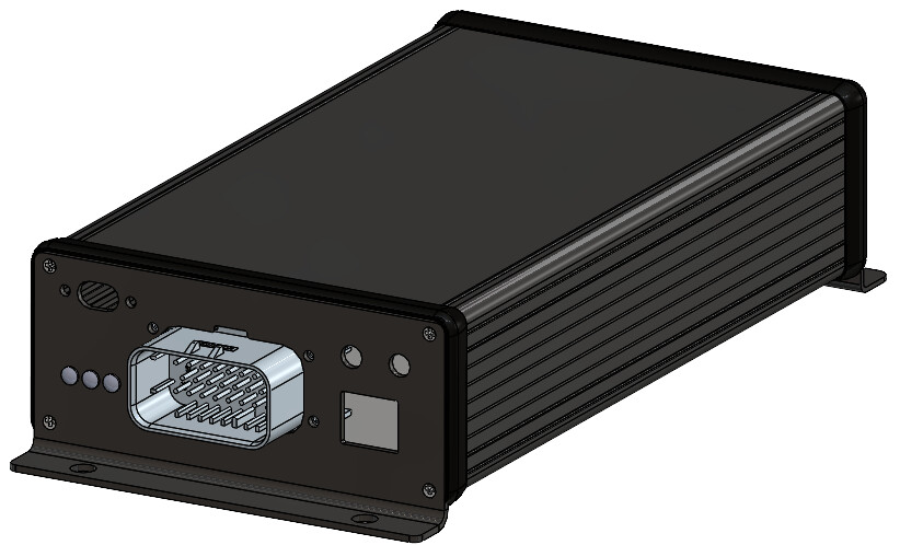
Otherwise I’m thinking a AT04-2P-PM16 in the back panel to bring 24v in.
2 Likes
Nice faceplates!
Pin 2 for the WAS signal.
No reason not to bend up pin 3 and 7. Search the beginning of this thread and you’ll see others have done similar.
What’s the USB C port for?
USB C would be connected to the teensy for diagnostic & updates. Haven’t cut the trace on the bottom the teensy yet, but plan to. https://www.digikey.com/en/products/detail/adafruit-industries-llc/4056/9997694