What are these? My board did not come with them. Thank you so much
OhioFarmer64
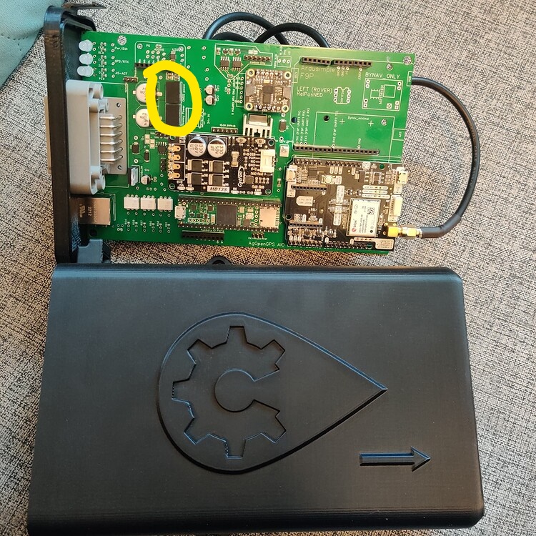
My name is Joel I’m farming out in Eastern Wyoming. Can you please help me? You have the exact same board as me. I’m getting it put together but I’m lost. Can you please show me your completed board? I had some pieces missing. I’m trying my best to piece it all together. Would you be willing to take a bunch of pictures of it and help me out? I haven’t found any pictures of the board like we have. Thank you so much. What are these that I circled in yellow?
Justin8366
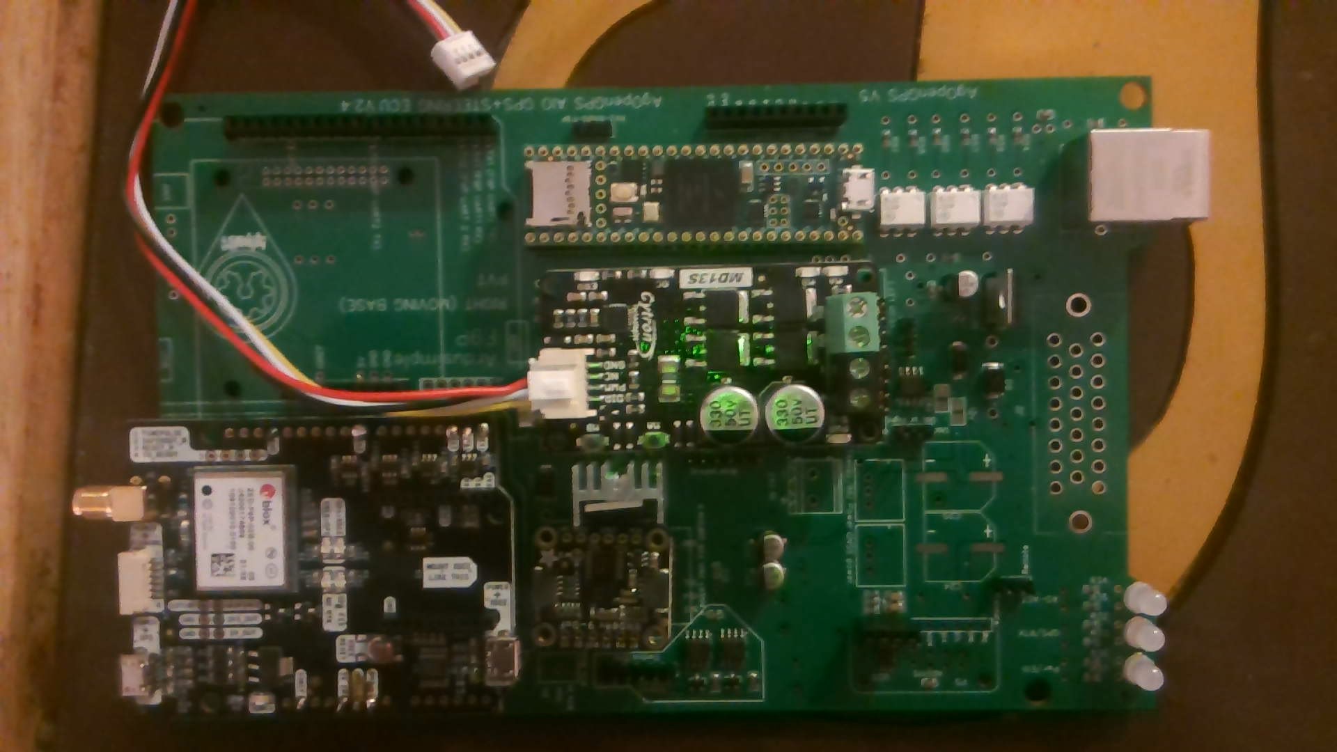
Thank you so much for the post. I have same board. Man I am confused. I got everything kind of put to together. I’m lost with where the wheel angle sensor hooks up. Any chance you could help? Or anybody. I’m so excited for this build just stuck. Heres what I got… Could you send pictures of your completed board
JD4955
I’m still fairly new to AOG, but I think I can help. The items you circled above are you voltage regulators. You’re going to want those. You should be able to match up the number on the board with the BOM spreadsheet for the part number.
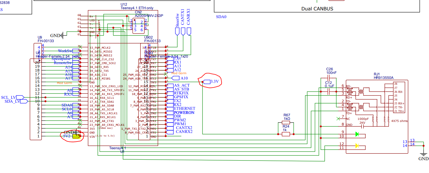
WAS comes in on pins 1 thru 4. If your using a 5v, 3 wire sensor you’ll do power on 1, gnd on 4 and signal on 2 all on the 23 pin connector.
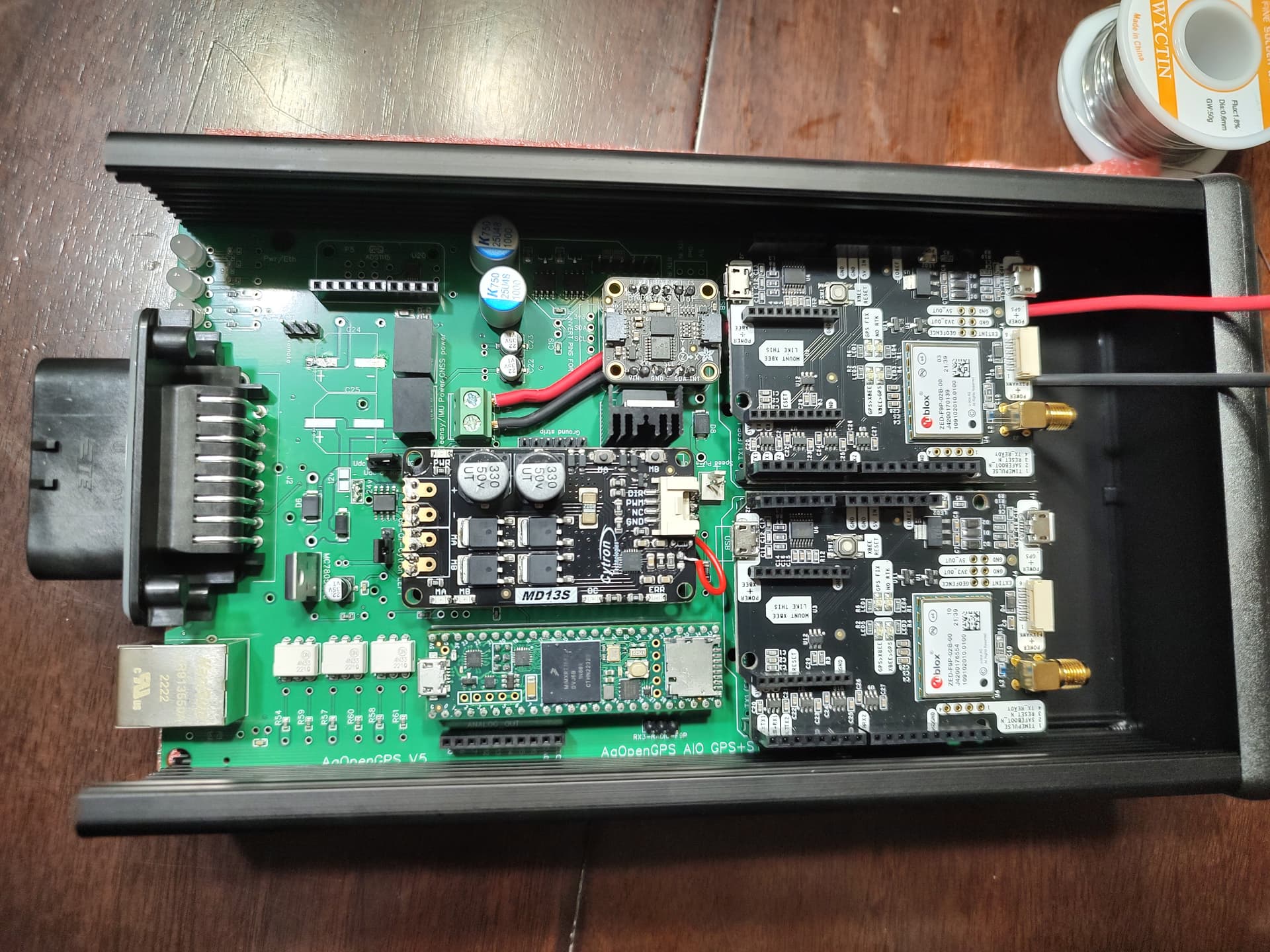
Looks like you are missing capacitors C23 &C24 yet and your F9P should be in the other slot
Thank you so much! My board doesn’t have any numbers for references the voltage regulators. Do you have those numbers? Man you have no idea how thankful I am that you responded! Can I ask you a couple more questions?
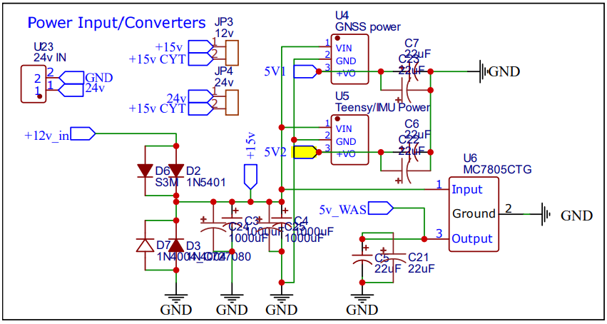
Teensy/IMU power and GNSS power both use a Mornsun K7805M-1000R3.
Thank you so much!!! I owe you so much! Do you have a pinout diagram for all 23pins for the ampseal?
There is a pdf in the Support folder that has the correct pin out. Here is a link to the wiki page that shows pin out, but be careful pin 2 & 3 are flip flopped. 01 Build All In One Board · farmerbriantee/AgOpenGPS_Boards Wiki · GitHub
Thank you again. I remember seeing that I just couldn’t remember where it was! Thank you! Where did you put your switch for main power and steering switch?
So which one is flip flopped. Is the actual picture diagram correct or is the list correct?
hi, these elements are K7805m-1000r3 converters that you have to buy and solder, after soldering check the voltage at the teensy and F9P contact, it may be that you solder wrong and you will have 12v instead of 5v, which will damage teenesy and F9P
Hi, you will show me exactly how you have made 24v on the board on top with Cytron, this cable and whether you connected anything with cables underneath. Regards
Thank you Oskar7210pro. I will definitely do that! This may be a simple question so I apologize beforehand. Those voltage regulators are both 5v regulators correct? Where does it step it down to the required 3.3v for the board?
Yes, both regulators are 5v, I’m starting my adventure with AgOpen myself, but I already know a little about it, you need to solder them and check at the teensy and F9P power inputs if there is 5v, if the voltage is higher, you have wrongly soldered converters, once you buy them, write a post on group and I’m sure someone will help.
I am from Poland, where are you from?
1 Like
Oskar7210pro,
Nice to meet you! My name is Joel. I’m from the US. I live in Eastern Wyoming. Thank you! Thank you for the information. I have heard from multiple people that both are 5v regulators and then a few people say the teensy4.1 controller uses a 3.3 regulation and the gnss uses a 5 volt regulator. You know why there are two different answers?
Sweet thank you!
Teddy,
Are you sure. Everything I’m seeing shows these both to be 5v. Based on the Std-Amp BOM and this schematic. Am I using the wrong documents? The boards I received from JLC came with both populated the same. I checked my board and I have 3.3vdc at the pins that call for it
Yes sorry I was looking at a Micro PCB which does have a 3.3V regulator on it.
The teensy receives 5V from the 7805 regulator. The 3.3V on the schematic is from the teensy. Teensy converts 3.3v from 5v input.
The micro requires more current to run the f9ps than is safe to pull from the teensy so it has a 7803 regulator to supply its power
Edit
Good information above on adding the regulators. BUT, make sure you remove the teensy and F9Ps before testing power after you solder the regulators in. This way you wont fry these expensive components if you have the regulators in backwards
1 Like