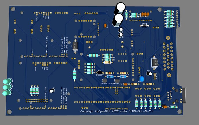
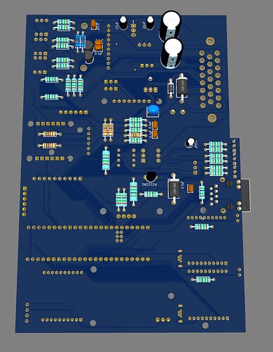
using the program Download Center - EasyEDA
Which are the parts that aren’t needed if I don’t want to use Danfoss or CAN bus, but an electric motor?
Jhmach, the cost of parts per board are $42 according to the BOM, that means by having only 2 boards assembled you save at least $126, which I think counts as “saving much money”. Am I missing something?
When ordering a PCB, JLCPCB’s “Select parts” page lists designator U4’s and U5’s quantity as 0, but the BOM says the quantity should be 1 for each of them per board. JLCPCB’s part list also says “inventory shortage” next to U4 and U5, but other parts have this next to them too, and their quantity is listed as expected. Why is this happening?
Also thank you for the AIO PCB!
@Jhmach thanks for the pre release and your instructions! Looking forward to getting the boards from JLCB soon.
Which code are you running on the All-in-one teensy?

It appears there are some motors being used that are 10 amp full load. The PCBs do not have large enough traces to carry that current. Below are 2 options to increase the current carrying capacity to ensure that the traces don’t burn through on a full load situation.
Micro F9P boards
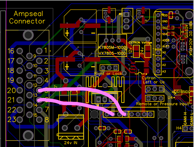
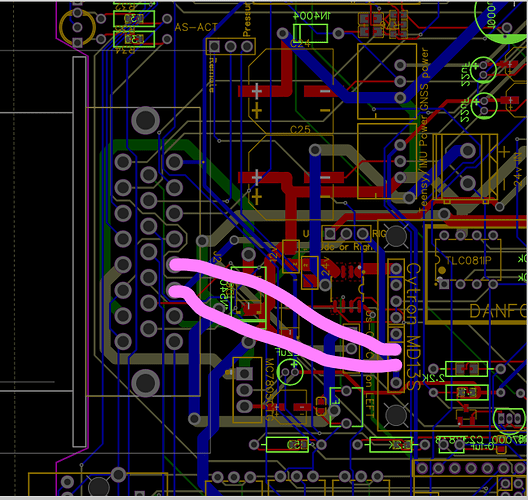
Just solder an insulated wire on the under side of the board as in these pictures.
Wire calculator shows 20ga minimum wire size. I would use 18ga for safety factor.
Below is the routing for the Standard F9P boards
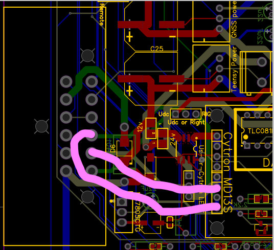
Are the traces to the cytron wide enough then? (Gnd probably but not 12v?) Or should we ad another wire?
Thanks, @Jhmach for all your help. Due to the shortage of parts for the Danfos valve and canbus, could you add a copy of the BOM for those who are not planning on using either?
Ground is connected to all 4 ground planes
Was talking with /bunched Emmanuel today about maybe ordering pcbs for motors with 2oz. copper instead of the 1oz. default
This will make it safe for 7.6 amps of current at 12 volts according to pcb calculator.
Phidgets motors apperar to draw 1 to 2 amps, but the larger, higher amperage motors might need more copper.
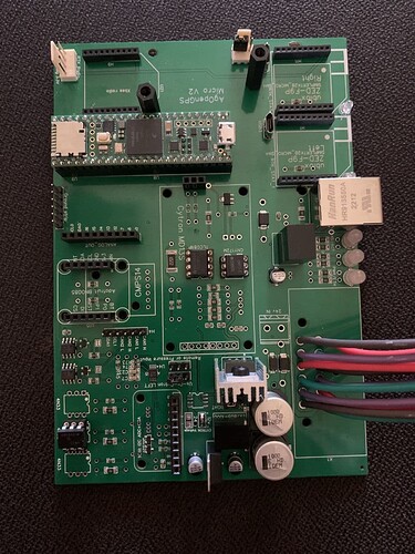
Anyone has a picture of a finished Pcb?
Always nice to see how it will look like when your done soldering.
First PCB for testing, micro version deustch connector.
Next week I will have the ones I ordered now, when they arrive I will post some photos
Just a question, a lot of parts like the tiny resistors are not in stock. Can we add normal resistors in the trough hole’s? or do we really need them?
I have a lot of spare parts for PCBV2, but can i use them in this board?
- 4n33
- Cytron board (Dont know why the TLC081IP and the CNY172M are for)
You should be able to use your optos, the cytron is same old. The CNY is for speed pulse output and the TLC is for danfoss valve control.
And resitors??
It’s hard to comment on which Rs you could leave out according to your individual needs, you’d have to study the schematic, but there are duplicate through holes ready for almost, if not all of the SMT parts. TOP layer assembly is SMT, BOT layer is through hole.
So if i understand correctly i can replace the tiny resistors by normal soldering resistors.
Correct??
I need normal hydraulic valve steering with lock true cytron and us cmps14 or bno
After a quick look just now, they all appear to have through hole options. Most are in the same location (over lapping) but a few are in different spots such as D7/D3, C24/C3 & C25/C4.
The through hole parts are on the bottom so that when you order and select TOP layer assembly, the TH parts are excluded by JLCPCB but you can still solder them to the top.
Thanks for your anwsers guys. Will be getting them next week and we will see what i still miss.
I placed an order at jlcpcb (5pcbs), however i have just received a mail saying that I have order a 2 layers pcb and the designed gerber is 4 layers.
They give me two options:
A- remove the inner layers to proceed 2 layers PCB
B- proceed 4 layers pcb per gerber file and send the supplement link for the cost difference
What shall I choose?
Do we need 4 layers?
