The Teensy is probably unfixable. The programming chip dies, so unless you have ability to replace that tiny sucker you’ll just have get another one. It sounds like it is related to the Mosfet with two people seeing the same issue when pressing drive. I don’t understand why it didn’t fail in initial testing though.
My Teensy failure was a regulator in backwards on a Panda board - smoke. I had a small solder bridge on a all-in-one board which revealed itself by getting hot. Everything survived.
Yeah it did hurt especially as i had it going so well the previous day, had it doing headland turns it needed a bit of fine tuning but was happy as a start.
Yeah ive got a spare board (was hoping not to use it and keep it as a spare and now i havnt got a spare😂) i need a few components to finish it off properly but the bulk is done. Ive ordered a new teensy aswell
Onwards and upwards 

1 Like
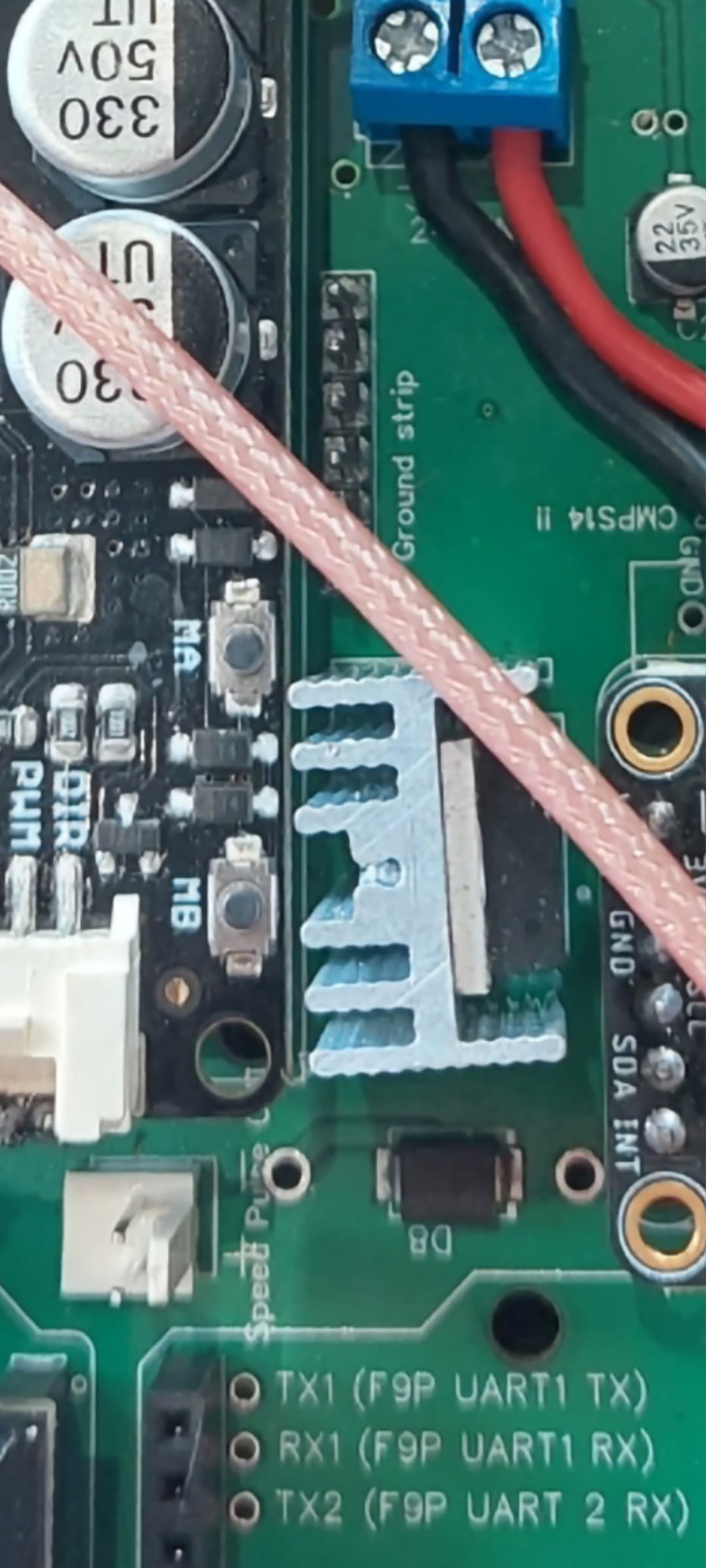
I had 2 boards done by jlcpcb and both of them are the same in that both the components are touching. I been back through pictures of others aio pcb’s and alot do seem to be either touching or very close indeed. Shall i add a bit of heatshrink between the 2 to keep them apart
The heatsink is there for a reason. You can get little insulating pads that go in between. Thermal grease is used to get the heat transfer.
Ok glad you have a spare. I had 5 built with intentions of building multiple systems but was going to offer you one to get you back going. I originally got 10 of the first pcbs and multiples of all of the components to build them but decided to build the Aio board. Not sure if anyone on here needed those old style boards or if it’s even economically feasible to ship them anywhere. That’s why I said you could use diodes from the original build bc I have lots of those among every other part and piece lol. I’m sure everyone is following the developments with this board and yours didn’t die in vain. It’s all a learning experience. I ordered some of the isolator shims for the heat sink so hopefully I can avoid the “magic smoke” 
Thankyou very much thats a very kind offer.
I order 5 aio pcbs with 2 assembled but wishing i had all 5 done now!
You can also desolder heatsink take out the pin that connect it to the board and attach it again. Just make sure it does not touch the GND
Ok, so the verdict was a bad ethernet adapter, really frustrating, but so happy to have it figured out. Thanks everyone for the suggestions
2 Likes
Thanks! You’re right, I didn’t need the modular ADS after all. I had the wiring mixed up going to the WAS. Working now.
biggest mistake everyone does  what am I going to do with 5?! you have neighbors
So I have some questions regarding the relay freewheel mod. So with the current pinout used for this, we have pin30/pin5 ampseal, pin85/pin7 ampseal, pin86/pin21 ampseal, pin87/electric motor left. So how do you know what electric motor left is, and if you hook it up that way, what happens if you invert direction in agio?
It doesn’t matter if it’s left or right, one motor wire, pin 5 for example goes through relay, the other goes direct from pin 6 to electric motor.
Could be pin 6 through relay and pin 5 wired direct, your just using relay to break the circuit in one of the motor wires.
But 5 and 6 are the motor leads, so you cant hook them both to the relay can you? I just cant wrap my mind around this, pin 5 and 6 power my motor, so the diagram calls pin 6 electric motor left, and pin five goes to pin 30 on the relay…
Have a couple questions. Does it matter which side of the tractor the WAS is installed? I installed it on the front left.
I went for a test run and everything seemed to be communicating and working properly including the motor, but now the motor won’t work. Any ideas on what it could be. I’m still getting power to the cytron and don’t see anything burnt on the board.
Do you mean the motor was originally working but stopped working when you put the was on the left hand side?
Ive seen some pictures of installs with the was on the left.
When you press the ma mb buttons does that fire the motor up? This tests the motor is getting power.
If so turn on the pwm drive function in the steer screen and toggle left to right with the arrows. The ma mb lights on the cytron should light up and the motor will spin if everything is talking .
Is your was setup correctly, does the wheels on the screen move the correct way when you turn the wheels.
Check what steer activation you have, 'none switch or button ’
1 Like
Hello,
First thank you to share all those information and sorry for my English, I’m French…
I’m begging the mounting of a standard all-in-one PCB and I have some questions :
- if the heatsink is not at the ground, it’s OK to touch with the transistor, no need to “unplug” the heatsink right?
-about the right side of the PCB “moving base”. I saw that there are some holes in the middle which are marked “1k” on the opposite side. Do I need to solder 3 resistances? Same question about the capacity C14?
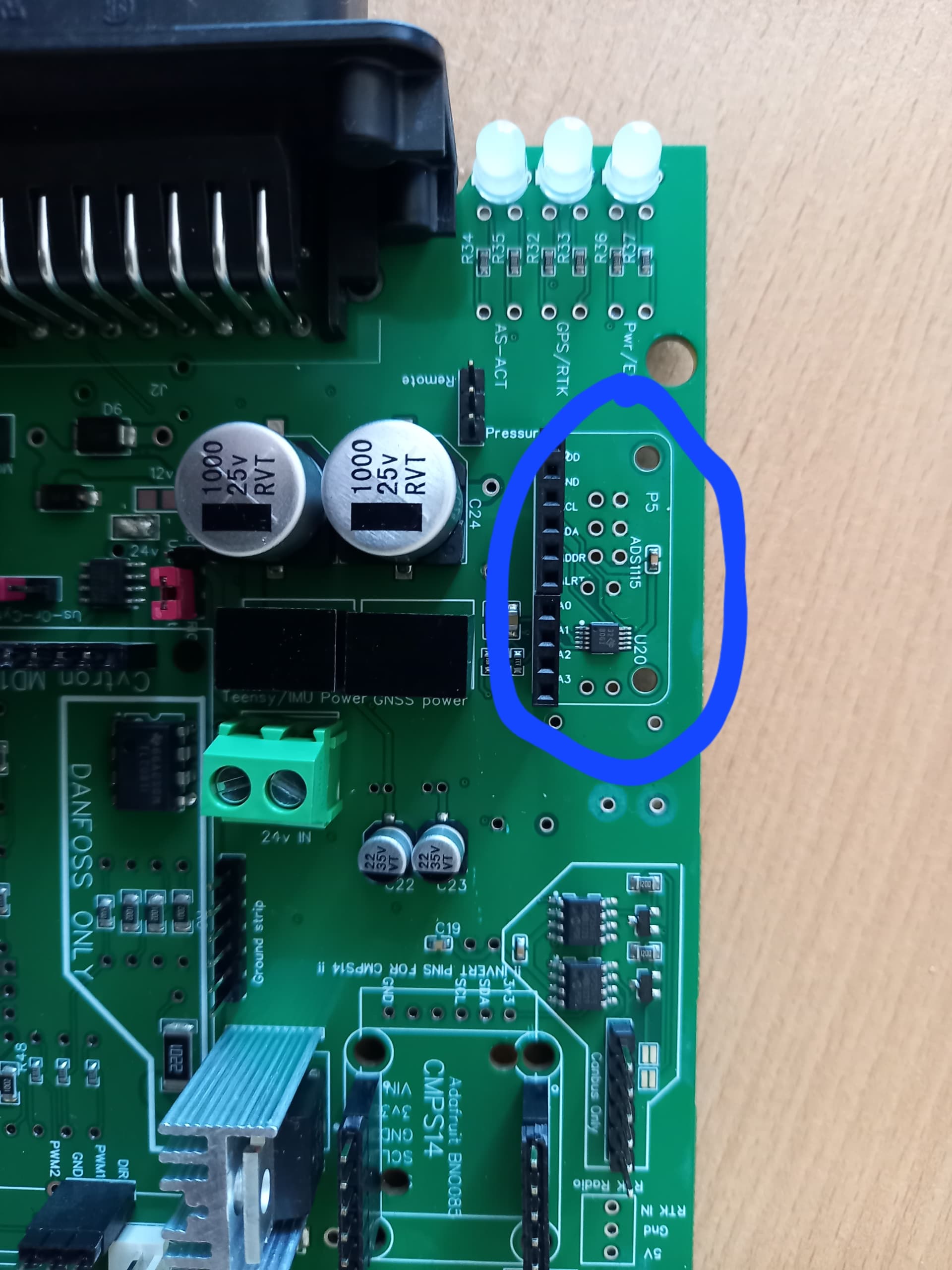
-concerning the ads115, I read that mine should already be on the PCB, but I’ve no resistance there, is it OK without resistance?
Thank you!
You have the smd mount chip, no need for an ads1115. Im using a phidgets motor and single/imu, and i didnt add any resistors.Someone else will chime in on the other questions.
1 Like
Got the same board as me and i don’t have any resistors fitted there and mine works. Thats where your f9p goes.
As said you already have the ads1115 on the board so your good there