Ok nice!
Thanks for your answer.
And what about the heatsink? I think it’s much better if the transistor is in contact with it to dissipate the heat, but I’ve read that sometimes if it’s in touch, there is a shortcut…
I will probably have others question in the few next days, I go step by step reading the official AOG wiki.
Ive spent alot of time looking at pictures of others standard aio pcbs and the majority have the heatsink touching. Weather this is right or not i dont know. Its easy enough to separate them slightly.
They have been comments about it shorting out if touching.
The thermal pads are size TO-220 if you want an isolator and use the thermal grease like wland said. After del_boys extra crispy board I put one in just as a precaution.
Thanks for the help/suggestions! Turns out I must have changed the activation for the motor to ‘switch’ (I have none) Once I switched it back was up and running. Was in a panic trying to get it going for planting. Just planted the first field and all went well! Now just have to fine tune the end-of-row turning.
I have a V2.4 pcb that was acting up lately and quit working a few days ago. I found the 3.3v regulator that powers the f9p is burnt. I think the teensy is dead as well ( it is not recognized by Arduino IDE and pushing the programming button doesn’t do anything) so I ordered another one and waiting for it to arrive.
I changed it with another from another board that I had and tested the power at the F9p and I am getting 3.3v which is the right voltage. Any idea what might have caused the regulator to burn? Is there any other tests to do to check for to prevent this from happening again?
What might have caused the teensy to fail?
I tested the power at the teensy header and it is 5v as it is supposed to be, is there any other tests that I can do to prevent the new teensey from falling?
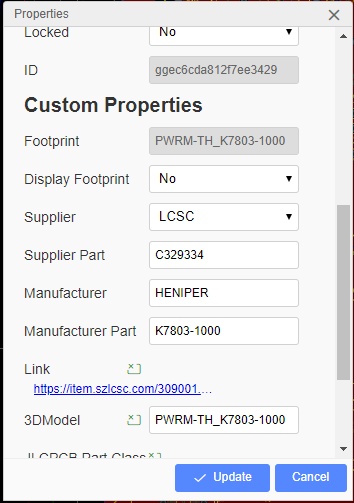
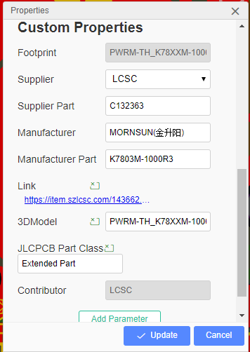
What is the part number for this 3.3v regulator so I can order one more just in case?
how many volts, if any am i supposed to have on Pin 8 on the ampseal? i had to take the plug apart yesterday and the system had been working beforehand, but now i can not get the system to engage. I have 12 v at pin 8 for the steer switch. the pcb looks fine i can’t see any burnt components and all the wires look fine too. The system powers up and everything shows up on my computer.
I tested my pin 8 steer switch a few weeks ago and i got 12v i think from mine, its the aio standard pcb.
What are you using to engage steering switch or button or none
Ok so then i must be having a software issue. I am using a momentary rocker switch, I checked it and it is working as it should and i have the button option selected in the computer.