I think it is U20 but check part number.
Yes it is! U20 I see now, it is tiny!
I have the 6 pin header on under the Teensy now, what plugs into it?
When the PCB has the 2x3 socket, you should solder matching pins to the Teensy. [PJRC] expects the header on the Teensy side, but both ways are possible.
2 Likes
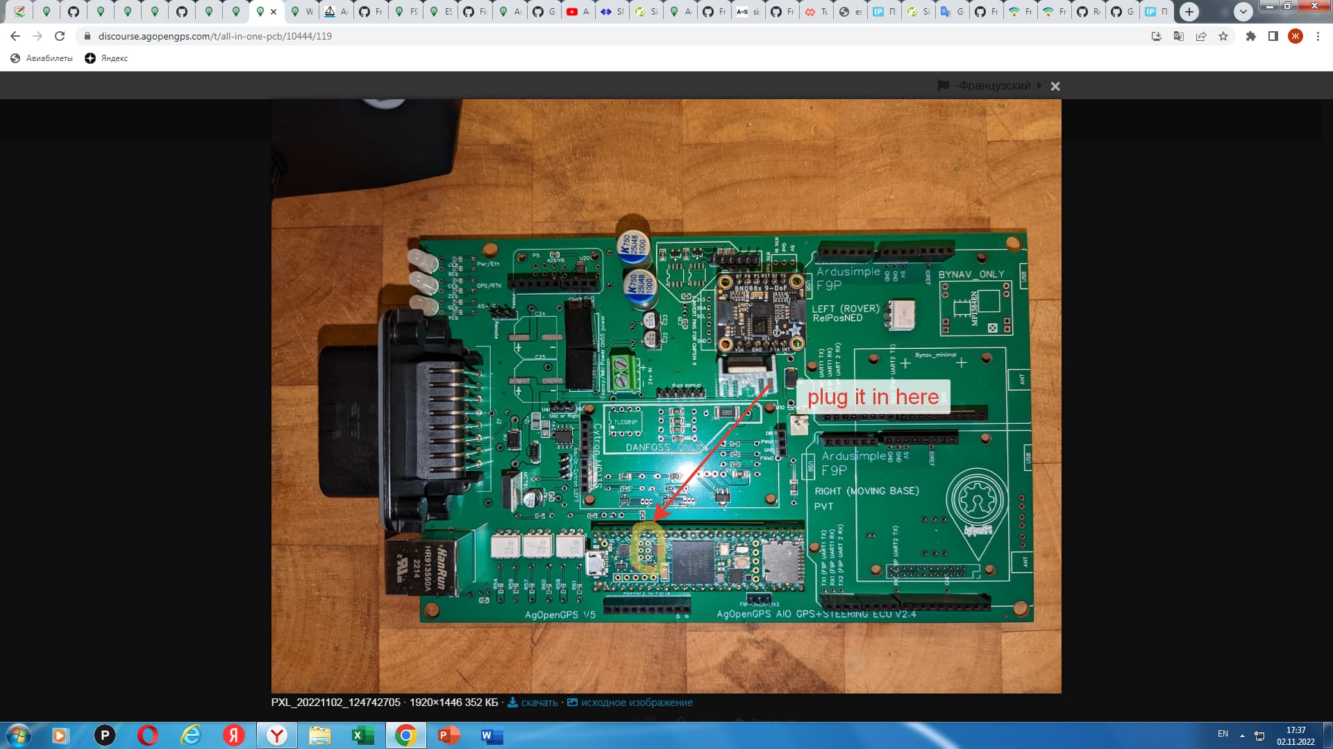
Do it like this. Then you can put the short end of the pin connector into the socket and put the teensy on. The long pins stick up through the teensy. then the 2 pieces are fully mated. Then solder
1 Like
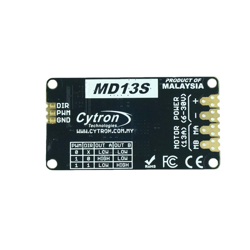
Is there anything to note about connecting the Cytron MD13S?
1 Like
Where i can find schematics for all of this? There are too many questions. Where are You buying Amp connector? What are pinnout from a pcb?
EasyEDA gives a lot of details. If you hover over the pin outputs it gives a description.
I bought the Ampseal connector from Digi-Key:
Does anyone happen to have the schematic file for this board?
Go to the Google Drive links in the very first post. There’s a zip file in each link that says something about BackupProjects. Inside the zip file is a json schematic file that Easyeda can open and show you.
3 Likes
Found it!
Maybe stuppid but i still wonder how to connect the cytron. On pcb version 2 its simple but no clue how to do this on the mico board. Any pictures anyone?
2 Likes
Any link for the correct headers?
The 3 pin end are there pre drilled holes in the Cytron, doesn’t look to be?
And how to get 24V to the Cytron?
I see the 24V in screw terminal, but cannot see how this links to the Cytron?
I’m sorry, I misunderstood the question.
So need to get another cable into the 3D printed box to bring in an external 24V?
And need long header pins with a screw terminal on top to take the 24V+?