Think i will use cable to put it in the headers on the pcb.
If I only use one FP9 board, do I need the right one or the left one?
1 Like
Use the right one. That’s where corrections are sent
2 Likes
If we use the 24V ‘in’ terminals do we need to solder the two contacts on the PCB near the Cytron?
Circled in blue below:
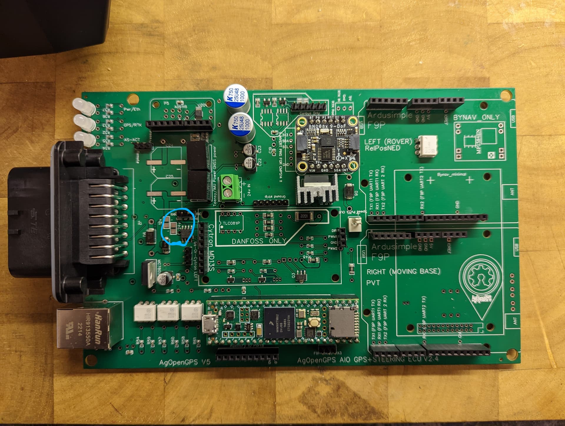
Solder the 12V jumper to use the PCBs main 12v power or solder the 24V jumper to use the “24V in” terminals. I think you can input any voltage compatible with the cytron.
1 Like
my plan is to use one of the Ampseal’s free pins (I’m not using CAN) to supply 24V (from 12/24V step up converter) through a wire straight to the cytron. so the step up converter’s output will be connected to the ampseal plug and from there with a wire to the cytron.
now my question is: how would you supply 12v to the step-up converter?
- there’s the +15v pin on the board which has the advantage of the capacitors and the diode built in but the current has to pass through some narrow PCB traces.
- the other option I see is use directly (obviously with a 10A fuse) the 12v of the tractor’s battery as supply for the cytron. in this case there are neither capacitors nor diode but I could also avoid the narrow PCB traces.
I’m using the phidgets motor on 24v.
would be glad to hear some opinions on this. I want to be sure not to burn some PCB traces if the wheel motor is at full load…
But that is not obvious when looking at the PCB ?
It say Rover for the Left one.
To make it easier for people not familiar with Dual setup it could be better to name them (Dual Rover) by the Left, and (Moving Base)+(Single Rover) by the Right one
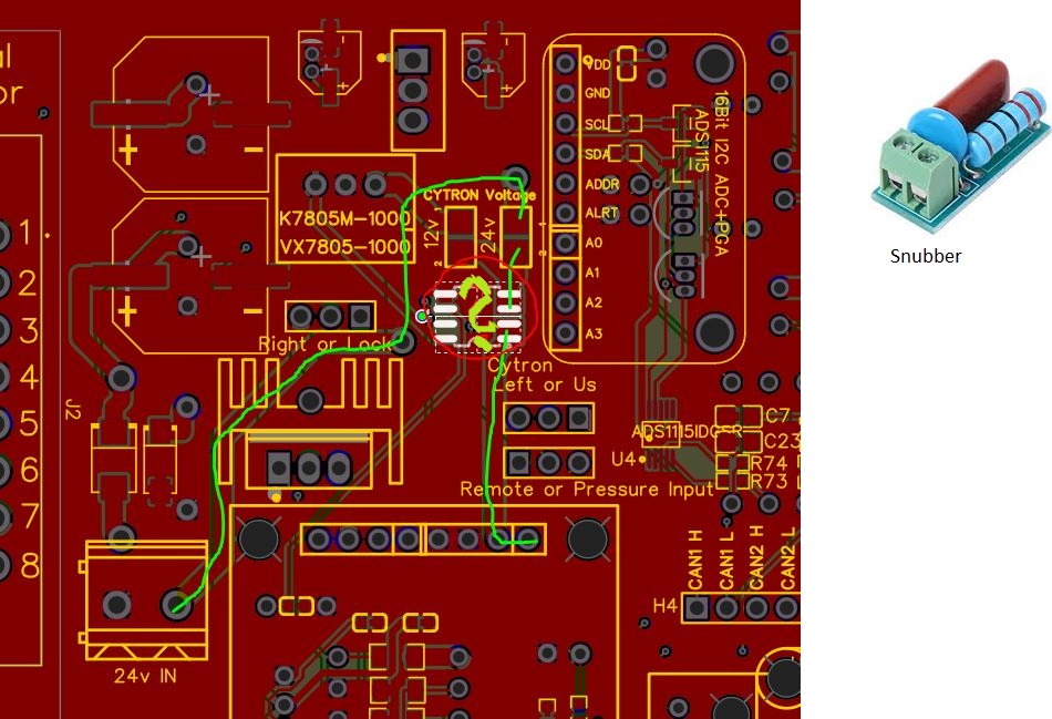
I would also power the Cytron directly. What amazes me is that all the power for the Cytron has to go through this tiny chip (ACS712ELCTR-05B-T) I have no idea if it does anything good or if it can be bypassed. Maybe someone with a clue can say something about it. I have Jake Hunter’s first Teensy PCB up and running. If there are very fast steering movements, the Teensy sometimes rebooted. I will try to make the supply of the Cytron as independent as possible. And will add a snubber.
1 Like
ACS 712 can check the current consomption of the motor and with AOG we can define a limit to stop autosteer
3 Likes
Where can we find this Auto_gps_teensy_v5_5 ?
Or the right .ino files for this board?
Support folder
5.6.2?
Most recent version of .ino files should be in v5NoJob
1 Like
It’s a Beta version, under development!!
Last stable pre-release is 5.6.15
Is there any provision for an on/off switch?
No like old pcb, but you can add a power switch in a free panel of your tractor, we thought this so you can place the box anywhere even if you don’t have easy access to it
1 Like
Is there anything to change in the ino?
Panda works, but I can’t get green autoguiding on Agio and the pcb diodes don’t light up
No. Use the one in v5fixes.
Make sure when you connect the ethernet cable, that you send the ip address even if it is correct.
1 Like
Thanks.
Imu and GPS are now green in AgIO.
But Autosteer is white. (and AS-ACT diode is off)
Is there something special to do on the pcb?
1 Like
If it receives wheel angle, it will go green. Make sure WAS is connected correctly.
1 Like