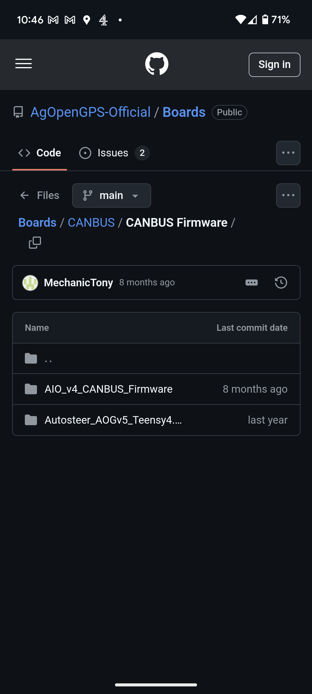
On the early version of Canbus code you need 2 Canbus as you describe.
But Tony updated his AIO Canbus code and added the Button engage, so it’s now just one Canbus, the Green one behind the seat.
On the early version of Canbus code you need 2 Canbus as you describe.
But Tony updated his AIO Canbus code and added the Button engage, so it’s now just one Canbus, the Green one behind the seat.
Thanks, I’ve seen that someone with Tony’s board plugged CAN 1 into the 40 pin connector and CAN 3 into the black connector on the rear column, I imagine it was an older software version. In CNH the automatic steering is on the CAN3 bus and the armrest buttons are on the CAN 1 bus according to a diagram that someone posted on telegram. If Tony has updated this, it would be much simpler to have just one CAN for everything.
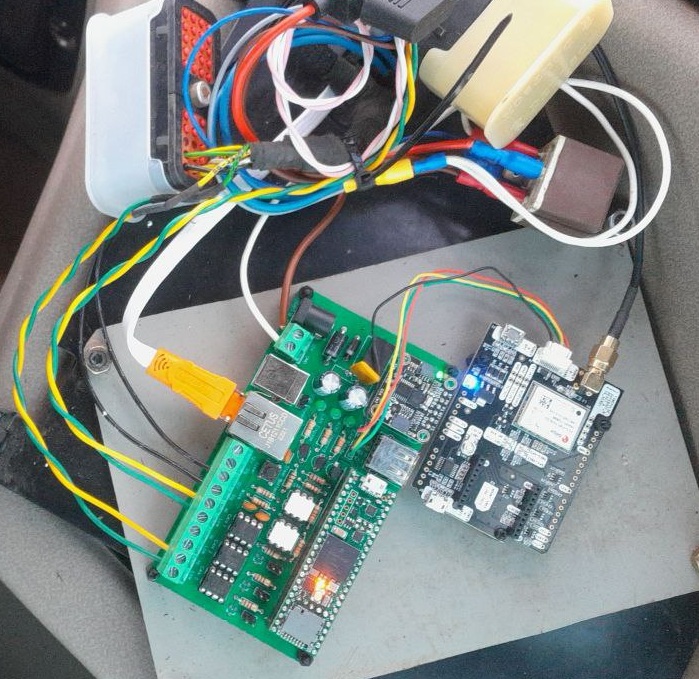
I have a 2.5" PCB that receives power between pins 22 and 23 of the Ampseal. I calibrated the WAS and the valve with the PCB connected to the CAN line, but when I start the tractor, the LED doesn’t light up and nothing works. It seems like it’s not getting power. I detect 0.46 V on both voltage regulators when there should be 5 V. I’ve tested the Teensy on another board and it works, as do the F9P and the BN085. Does anyone know why there’s no power coming in from the socket? What have I burned?
Just try to add more solder on ampseal pins, I had same issue the top and bottom layer are not connected propertly through hole, worked for me, let me know if it works for you!?
Thanks for the advice, pin 23 wasn’t making contact at the top, I heated it well with the soldering iron and the tin passed through, now it works perfectly.
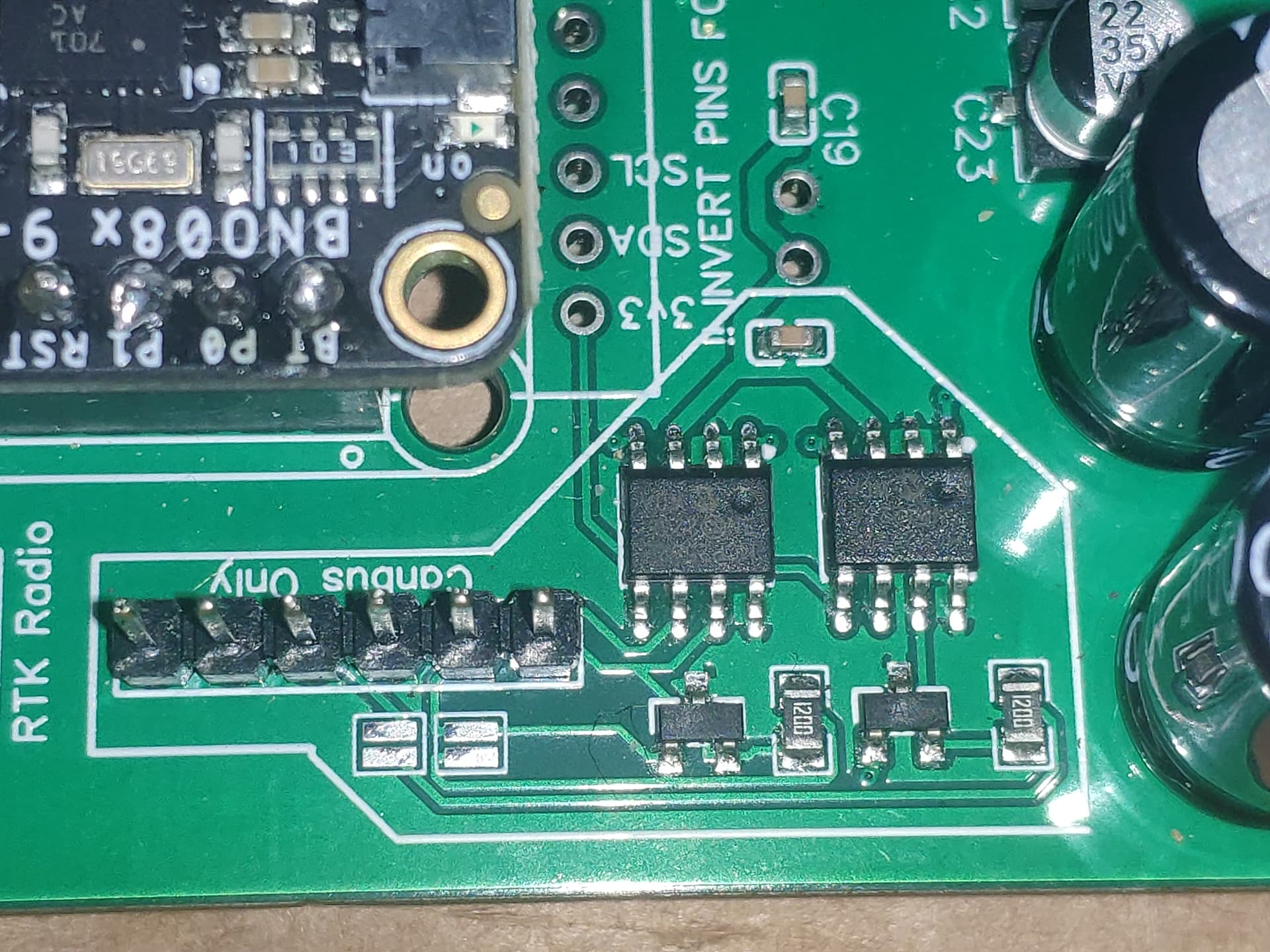
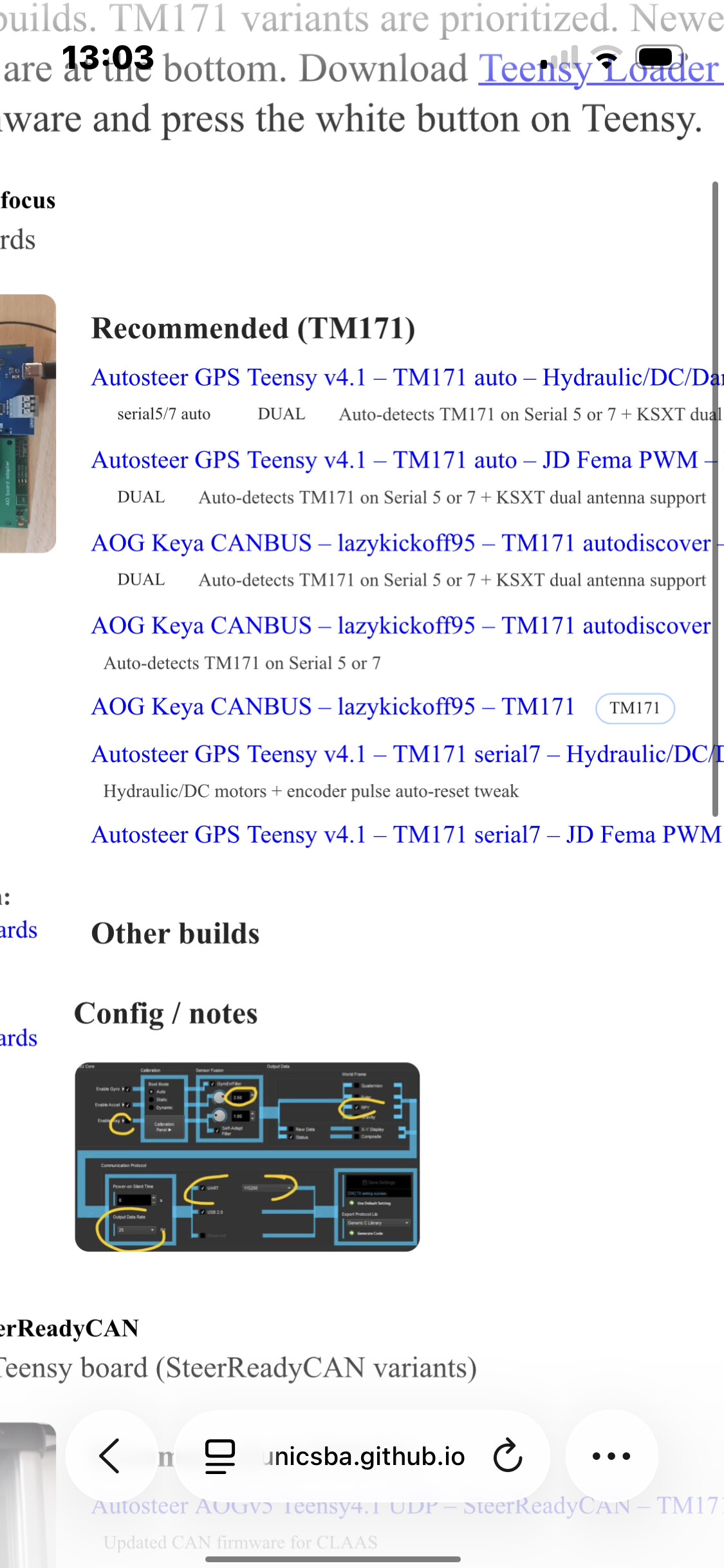
Hello, has anyone tried to connect TM171 instead of BNO to PCB 2.4?
The v4 firmware worked for me.
Can you tell me more? The TM171 is connected to the PCB. What software version is it exactly?