I had the same problem, I bought the engine and the sensor in the opposite direction and it was fixed.
1 Like
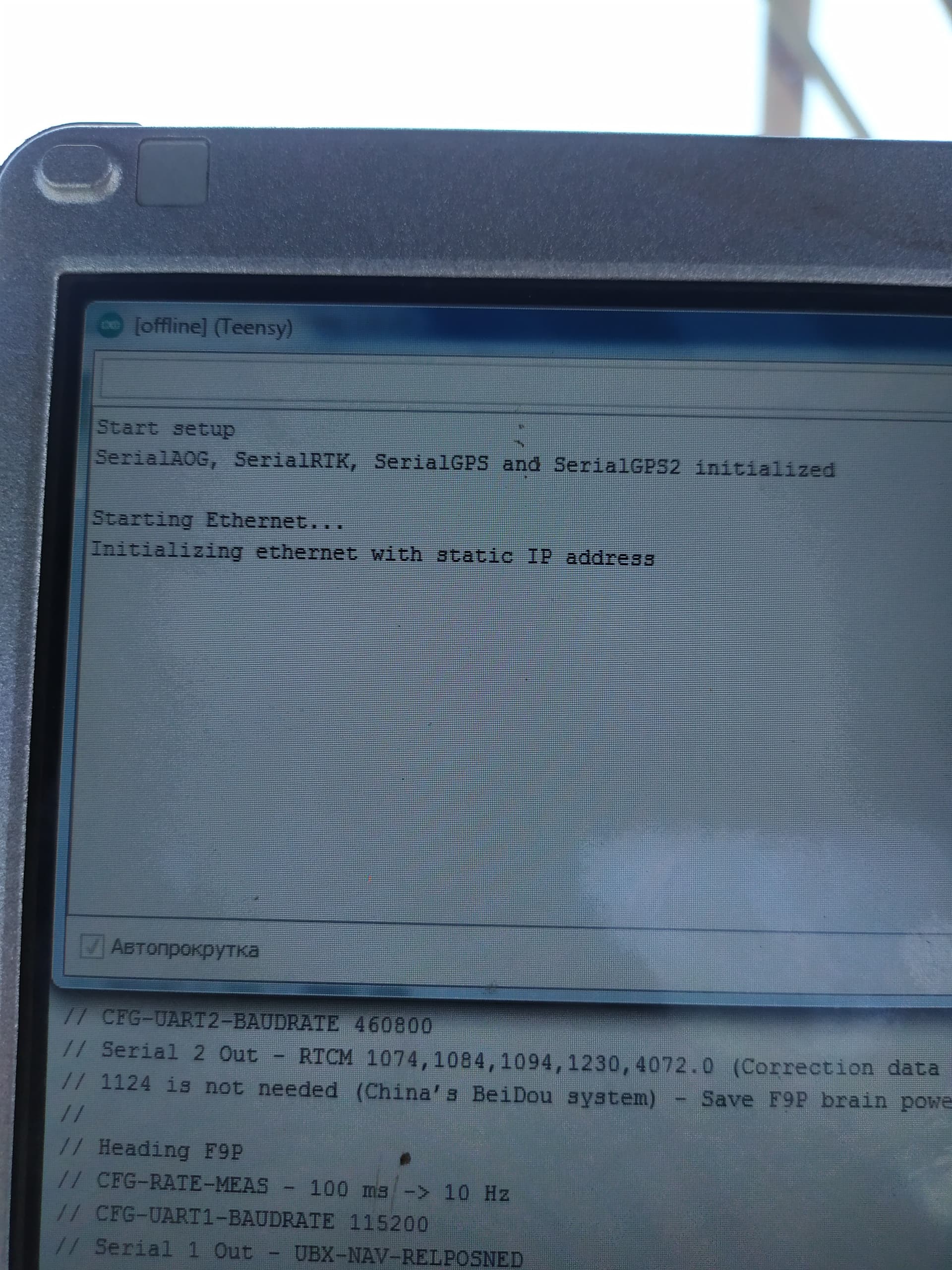
I made a port monitor with a working version with an IMU and a dual antenna. With a dual antenna, there is no top line with port 888. Maybe this is the reason why the motor does not work? Can you advise something.
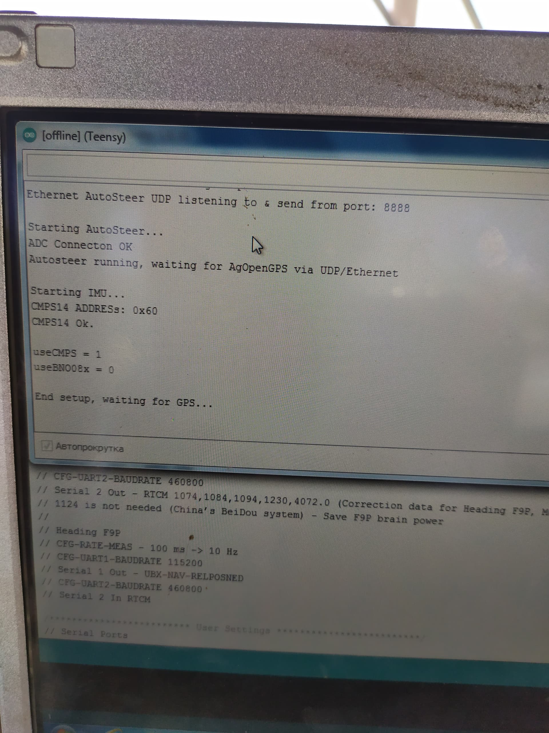
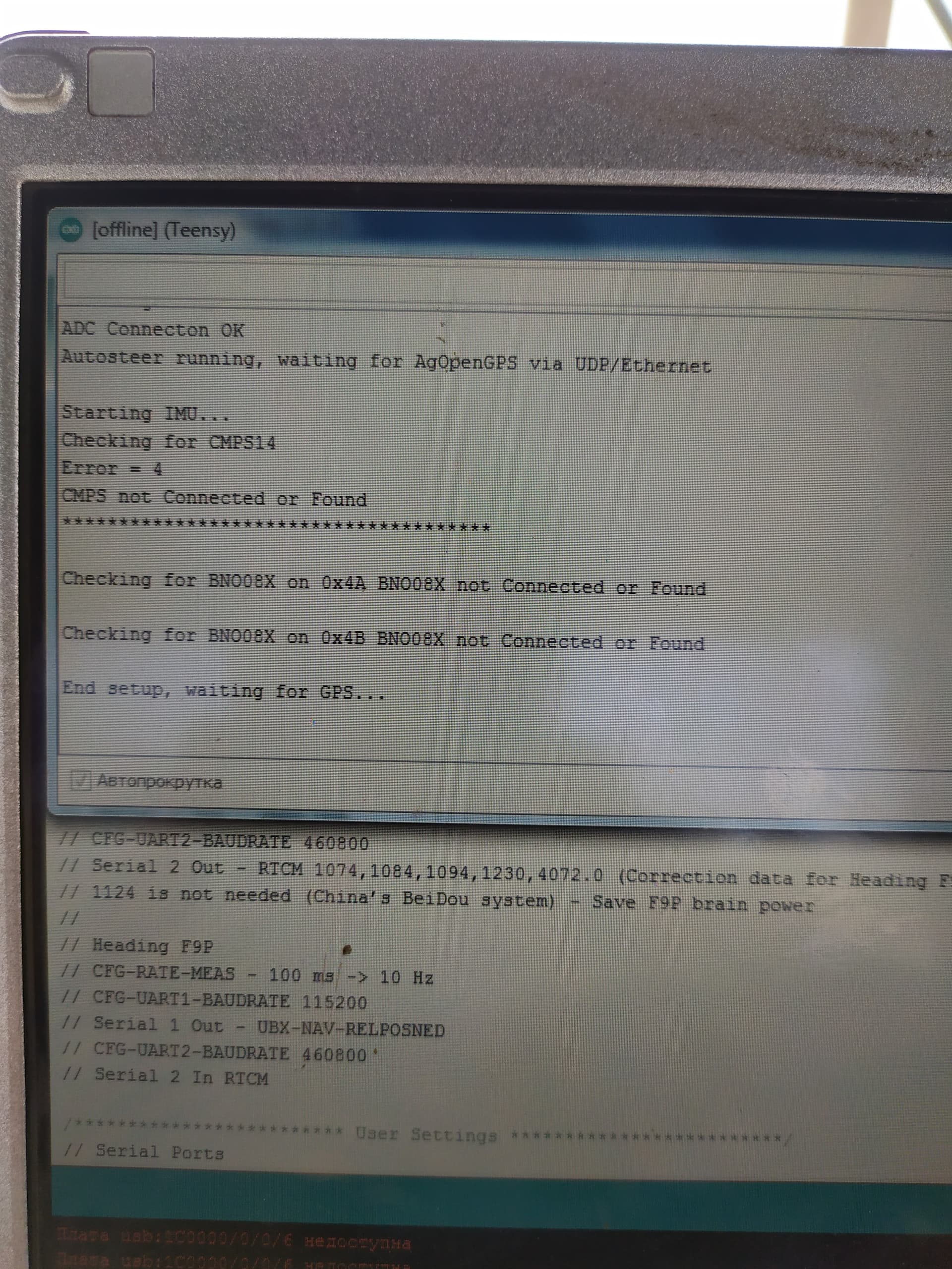
Here’s another top port with a dual antenna.
When you drive around, do you have speed showing in aog?
no, it doesn’t show.
The fact is that I just connected another laptop that worked for me in a tractor with IMU, with version 5.6.2, the autopilot worked for me. I’m going out into the field now, before it’s dark, and I’ll try. And then I’ll find out why I couldn’t do it on a laptop with version 5.6.15
I tested a double antenna in the field today. The autopilot worked only with version 5.6.2. With version 5.6.11 and 5.6.15, the autopilot does not turn on. There were glitches in the program with the dual antenna turned on. The tractor often turned in the opposite direction. When I switched to FIX mode, everything was fine. With a dual antenna, it turned on the 2D mode. Did not quite understand. Antenna wires in the direction of travel where they should be directed. I have them pointing backwards.
In the later 5.6 versions speed is not calculated from fix until the speed indicated from the VTG from the GPS is over 1.5 kph. The VTG speed is is disabled in the .ino files and is not needed in 5.6.2 but for some reason it is needed in the later dev releases. Last stable release is 5.6.2.
1 Like
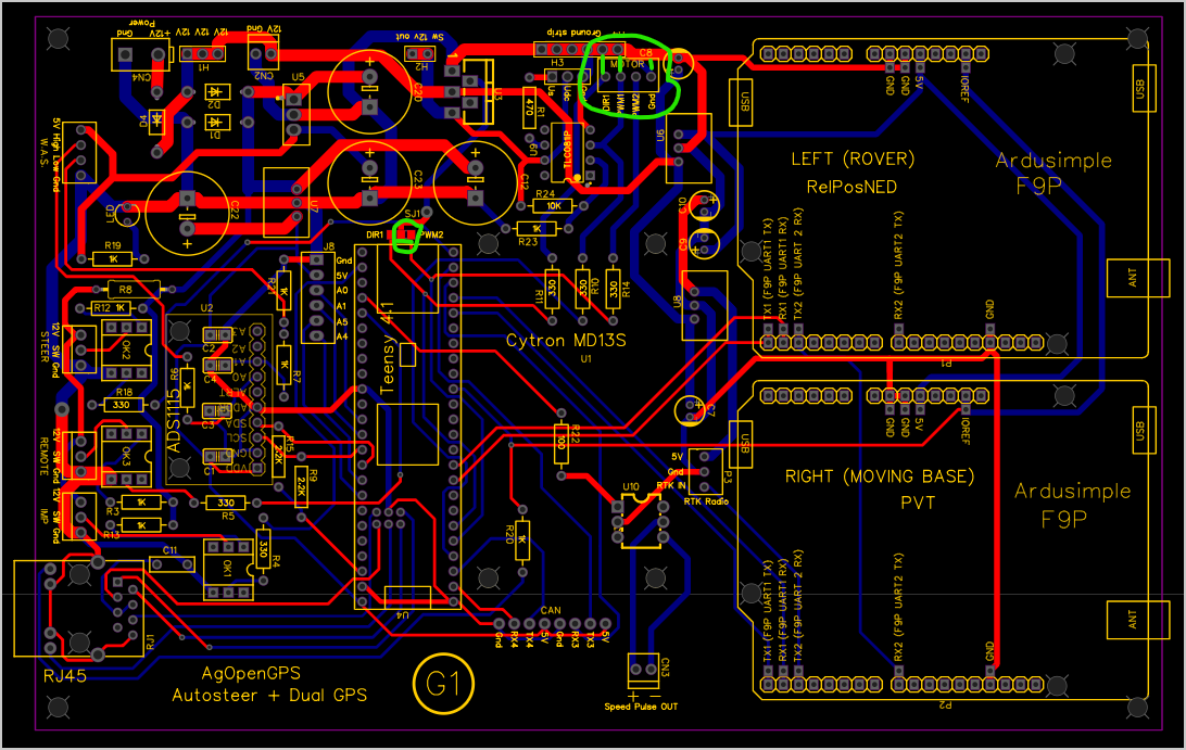
As I said before I am using a steering valve setup. Could someone show me how to wire the cytron md13s correctly? Do I only need to wire the DIR, PWM, and GND wires to the board? On the jumper pads should I solder the dir1 and center pad together? Also on the pressure sensor, according to one of the diagrams it shows to connect the ground to the signal wire with a 250 ohm resistor. How does this work? My pressure sensor has three pins.
Yes Dir, PWM1 and gnd. Connect to pwm2 on the jumper. not dir.
Ok thanks! I’ll try that, I think I had the jumper wrong.
If you put the jumper on dir it will be turning the valve power on and off when it changes direction
Could you explain? If I’m seeing things correctly, if I solder the middle pad and pwm2 together instead of dir, the dir wire coming from the cytron is now connected to nothing and nothing is connected to the pwm2 terminal on the PCB??
Yes jumper the center and pwm2
then connect Dir, PWM1, and gnd to the cytron. NC on the cytron gets nothing.
As soon as you engage the steer switch, PWM2 gets power, which powers the BTS442 sending 12v to the 6/2 valve or whatever you are using, and it powers H2. You can bring power to the cytron from H2 (12v sw out) if you don’t have a safety valve. Then cytron will have output power from the BTS442 when the switch is engaged. Not needed, but just a safety of sort.
Hello. What antenna are you using on the base? And what is the distance to the range of the transmitter.
I am just using the 5dbi that comes with the rfd radios. It works for several miles on open flat ground. I have a 9dbi omni (looks like a broom handle), which is the legal limit here in the US at 1 watt, but it has been loaned to a friend since I’ve had it. They are supposed to be good for something like 40 miles on open ground.
Any updates on the timeframe of these Teensy boards?
Soon!!
1 Like
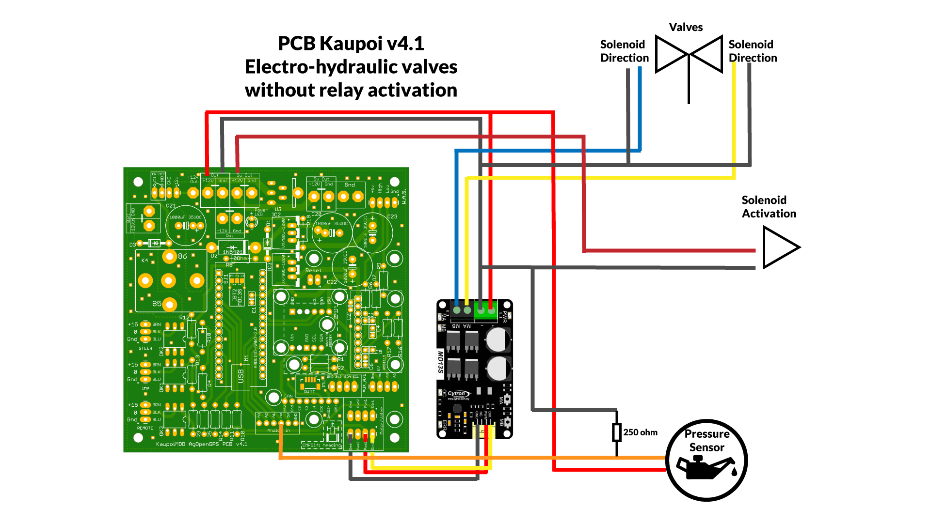
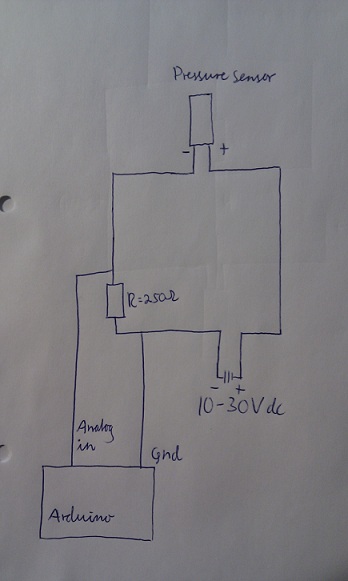
For some reason it did not work right away but now everything is working except for the pressure sensor. According to this diagram, it shows to connect the ground to the signal wire with a 250 ohm resistor. My sensor has three pins so should I just forget the ground and connect it to the signal or still connect the ground to the sensor and cross it over to the signal as well with a 250 ohm resistor? Maybe it is supposed to work without this resistor…
As a clarification I am using the dual gps board.
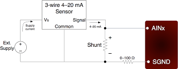
This is the connection diagram for the 2-wire sensor, the 3-wire ones have + gnd and signal output, the 2-wire sensors are connected to the gnd of the 250 ohm sensor, but the 3-wire sensors are connected to the signal output.
We convert the current to voltage by connecting a 250 ohm resistor to the circuit and convert it to 1-5 volts at the analog input.
1 Like