So if i understood, when you set “dual” , it does’nt work, then you choose “fix” and you come back to “dual” and it works after that, right? very strange… I will test that tomorrow
and another question : WAS is a 4 pins connector, but mine is a 3 pins. Which one do I connect? High or Low?
For single/regular connection use 5v, high & gnd. When your WAS is isolated, use WAS signal->high and WAS gnd ->low and set according in AoG.
1 Like
I have two cards. I was able to run it on the latest version (5.6.1). The program also works with fix. didn’t work in dual option

Thanks for your answers.
But I think there’s a problem…
Indeed, heading working (but very jerky), but now “no RTK” leds blink …
With “dual” button, leds are off for the two F9P…
Why there is a “dual as IMU” button when we are in fix mode?
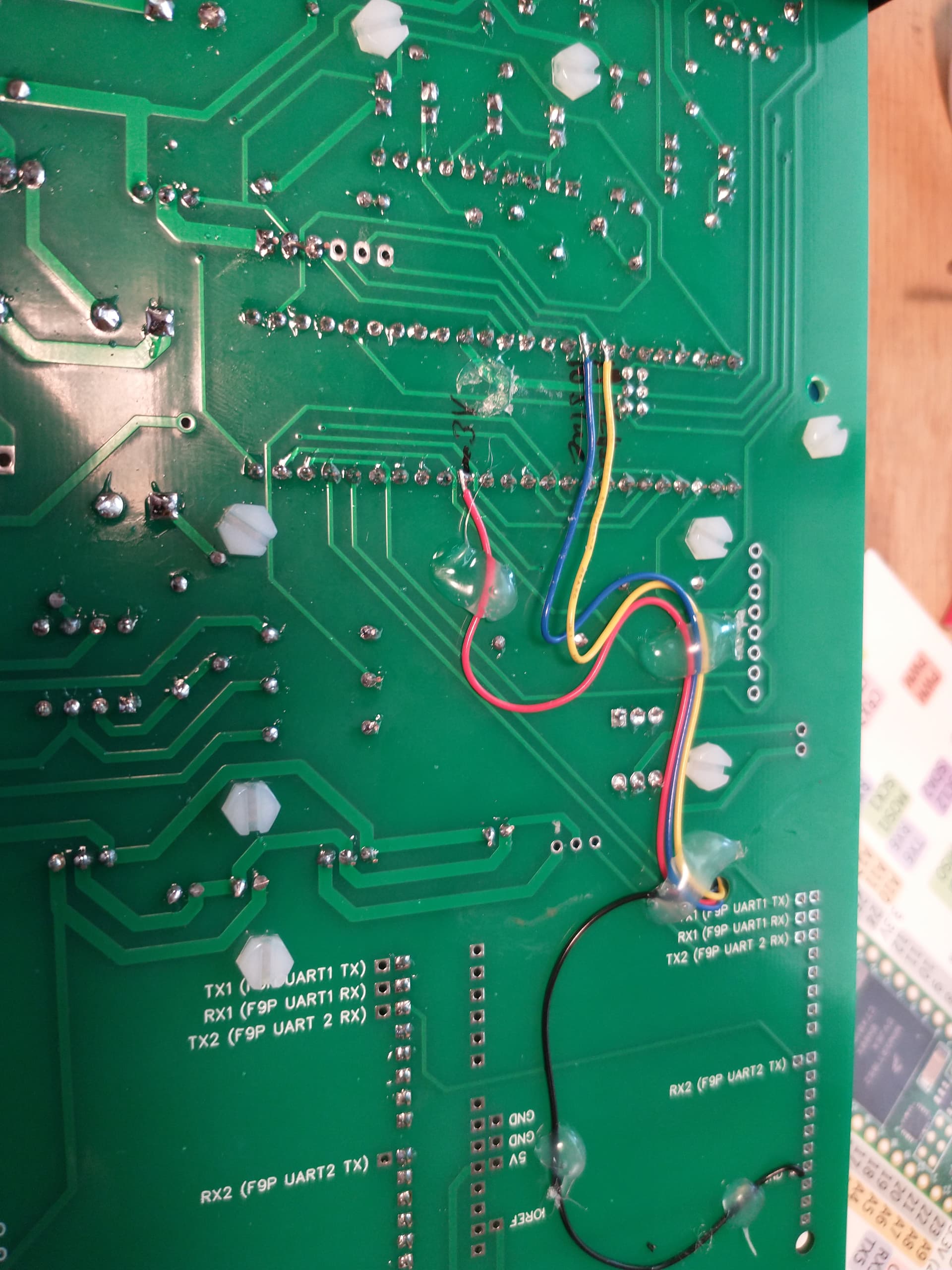
is there a 1.32 config for dual F9P? I configurated them directly with U-center, but I think I did mistakes…
Filled the configuration into the f9p module. On the rover GGA and VTG messages are disabled. On base included. Is that how it should be? Firmware uploaded 1.30
if there is a txt file somewhere, I’m interested
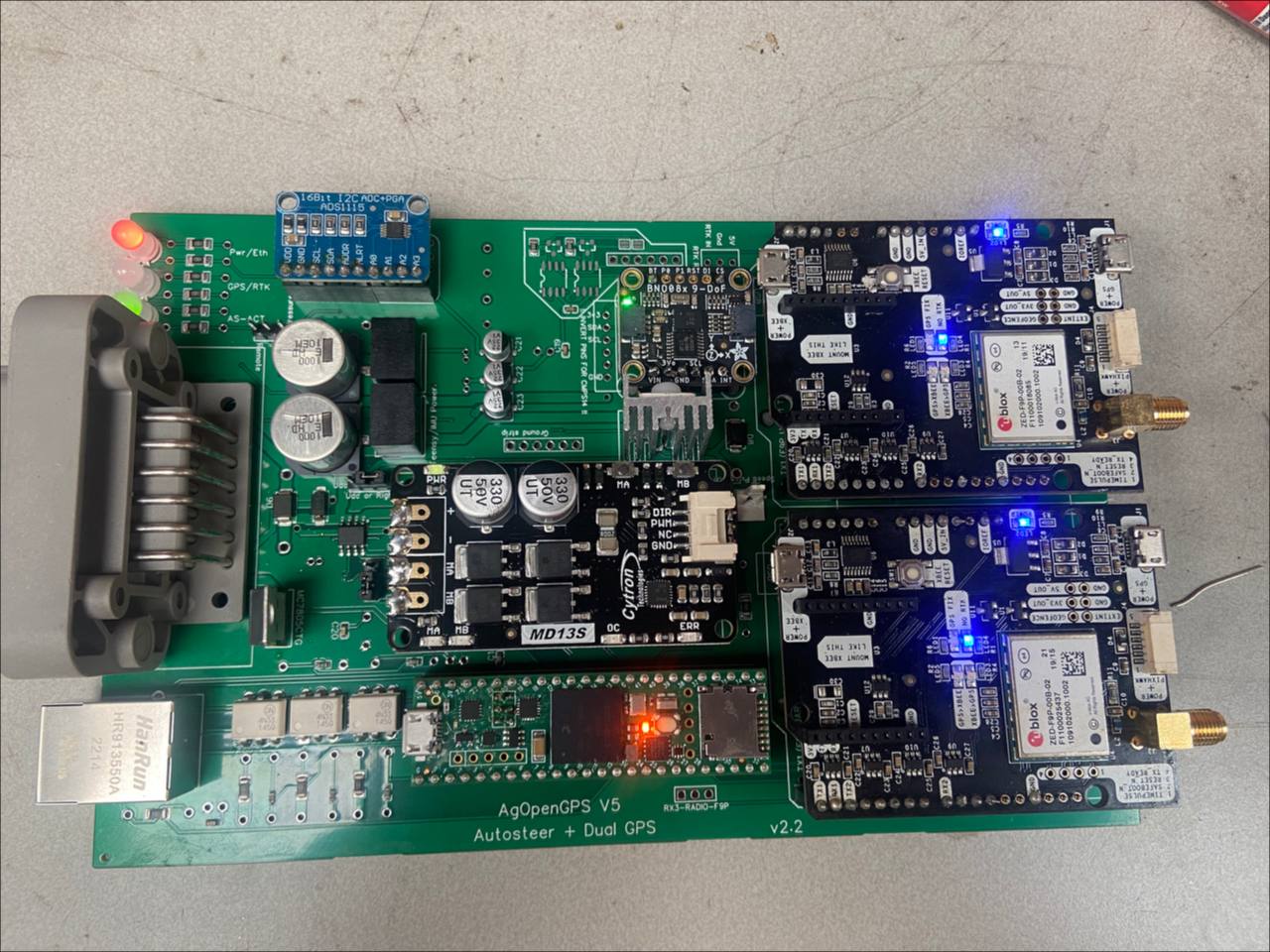
Here is how I added a BNO085 to the dual board. I also added the ACS712 at the USB end of the teensy.

1 Like
That’s nice work Jim. It looks good.
Everyone keep in mind that we are just about to release the 2 new all in one boards with smd or tht options. Richard is testing the v2.3 board that used the standard simplertk2b module, and I will be testing the new micro version. Both boards will have the same BOM except for the gps module. JLC will assemble it for you with headers intact. If there are any parts unavailable, you can add them yourself as through hole component.
I am hoping for testing to be done next week and if all goes well we will release them on github.
Both have footprint for bno08 and cmps14, plust acs712 with freewheel components for the motor guys and a FET for 6/2 valves etc. Richard has also added a jumper for the 24v motors and status LED’s for power, autosteer, rtk, ethernet and some extras.

9 Likes
Thanks. Timing is everything! I will try this new version on a future build.
Launched a dual antenna. RTC is. I don’t have an autopilot. And the direction of the tractor in the opposite direction. In the program, I switched to a double antenna. version 5.6.15. Maybe I’m doing something wrong?


click 2d and drive forward. If the antennas are backward it will give a reverse arrow but the tractor will point up
Thank you.
Does that include the hammond enclosure? I’m having a hard time visualizing how the micro board would be installed into the hammond enclosure? Seems like the plugs would be in the side of the case and you wouldn’t be able to slide the PCB into the tracks if that’s the case?
It is great to see that all the connectors are on the same side of the micro PCB, no need for small antenna extension wires!
No, the enclosures are different. There is a substantial size difference in the two boards.
when you talk about the ardusimple-micro board is it the simpleRTK2Blite board? the only advantage is that it is more compact which is not the case of its price.
Not the Blite. It has 2 uarts like the simplertk2b, but in xbee footprint. Yes it is just a smaller board is the only advantage.
We have an agreement with Ardusimple to do a groul buy to get a price lower than the simplertk2b. I think its 165 usd. After we test the boards we will post them on github and we will start the group buy
2 Likes
Hello all !
Sorry to come back with the same problem but I think my F9Ps are not configured correctly, the “no RTK” LED keeps flashing on the left board.
Can someone give me the manual configuration or a link for the txt file?
So I’m curious, how do these all-in-one boards work with the 24V motors?