Autosteer disengagement (torque measurement)

More information. Manually turning the steering wheel left it disengages fairly easily. Turning right I can’t get it to disengage hardly at all. I had the motor stalled in a high speed turning situation with a lot of force on the steering wheel and it would not kick out.

Something must be up with my install of the ASC712 on my board. I purposefully located it away from traces so they would not interfere with the current sensing. I will take it apart and try a different location on the board.

So I just installed mine about an hour ago. ACS712 on a 24v phidgets. So far so good. Only ran it down the road a little, so in the field might be different. Have it set to kick out at 25%. 20% would occasionally kick itself out. I bought the 5Amp version without thinking whether or not it would be good enough. Later I was reading about guys using 10-20 amp versions. See what happens I guess. :man_shrugging:t3:

Did you tap a motor wire, or the supply wire for the cytron?

Direction should not matter at all as amperage reading is read in code as absolute abs(), which means it is positive regardless of direction. I have the ACS stuck to the side of the V2 large power relay with tape with no interference issues. It should be tapped in series on one of the wires heading directly to the motor.

If you have 20-25% of ajustement for 5A version 10A will be divide by 2… so 10 -13% so more dificult to ajust some person claims about performance of ACS712 it always link to big capacity

Our electric steering consume less than 50W in general so the 5A is good enouth even if 12v version

For example in my case with electric motor 12V ~40W in JD 6030 with my ratio

for few angle 60% is possible like this

https://youtube.com/clip/Ugkx2-RC0cqOuH2XRde9jEP9IgivBsD-JBRI

But i need to set 80-85% to avoid trouble for big steering like U turn

It is inline with one of the motor supply wires. Maybe it is a defective unit. I will try switching it out also.

Just mounted the box in a nice neat location Monday night. Now I have to take it back apart. LOL!

1 Like

Just wait till you start adding modifying it, it never truly is fully apart or together :grin: Thought mine was finished then PANDA showed up.

2 Likes

Resolved my issue. I am using the all in one dual GPS board with the Teensy 4.1. The analog inputs are 3.3V. The ACS712 outputs a curve that is approximately 0 to 5 V with 2.5V being the neutral point (0 amps).

Since it was not ever close to zero point it would kick out going one direction but would never kick out going the other direction.

The issue is that the .ino for this board still has the zero for the signal at 512 when it was actually seeing 776 as the 2.5 V value on the analog input pin.

To resolve this I modified the autosteer.ino file to auto-calibrate the input zero point. This is done with three sections of code.

In the declarations I added two variables.

float sensorZero;
float sensorZeroVal;

In the autosteerSetup subroutine I added the following at the end

  // Current sensor?
  if (steerConfig.CurrentSensor)
  {
    //zero the current sensor as there is no current flowing thru sensor at this point.
    for (i=0, i<= 100, i++) {
      sensorZeroVal = (float)analogRead(ANALOG_SENSOR_PIN);
      if (i==0){ 
        sensorZero = sensorZeroVal;
      }
      else {
        sensorZero = sensorZero * 0.7 + sensorZeroVal * 0.3;
      }
    }
  }

Then in the autosteerLoop() I modified the code slightly to use the new zero point.

    // Current sensor?
    if (steerConfig.CurrentSensor)
    {
 
      sensorSample = (float)analogRead(ANALOG_SENSOR_PIN);
      sensorSample = (abs(sensorSample-sensorZero)) * 0.5;
      sensorReading = sensorReading * 0.7 + sensorSample * 0.3;
      if (sensorReading >= steerConfig.PulseCountMax)
      {
          steerSwitch = 1; // reset values like it turned off
          currentState = 1;
          previous = 0;
      }
    }

This works well and will work for an arduino with 5V analog inputs or for a teensy. You could even change the bit resolution on the teensy and it would still work.

6 Likes

And wouldn’t it be easier to provide ACS in the MD13S power line? Then the current will flow in one direction left and right.

1 Like

The code already reads absolute abs() value so direction does not matter.

Putting it in the motor line allows ignoring any power used to run the mds. So your set point for trip is based only on motor current only.

1 Like

You must NEVER send 5v to the Teensy.

Make sure the ACS712 is installed BACKWARDS in the power line going to the MD13S so its output is always 2.5v - 0v.

@CommonRail, Yes, I know this but I can’t get this sensor to send out more than 3V anyway to the teensy. However your solution sounds like a possible option also.

I tried a voltage divider on the output of the ACS512 to step it down to 3.3V max. I am not quite sure how the analog inputs work on the teensy because they had 3.3V on them and the voltage from the voltage divider did not work. ACS Out → 1K → Teensy A0 ← 2.2K → GND. This resulted in the teensy reading ~3.2V all the time.

would it be better just to switch to a 3v native sensor?

Or just send data, its hard to fry stuff with 1’s and 0’s

1 Like

In this case why not to use ADS1115 to an unuse pin to catch the voltage of the sensor ?

since the use of the zADS1115 library (ADS1115_lite) only one register can be read on the ADS1115

1 Like

All of these solutions sound possible. However the one suggested by @CommonRail requires no program change and is a simple rewire of the screw terminal wires on the board. I will probably try this next. Time to take it apart again. It will probably be tomorrow.

1 Like

I read cover to cover, disengagement is only mentioned as a needed item twice, but no mention of how to pull it off. They reused a trimble Ez steer motor for the tests, and did spend a disproportionate amount of time back calculating why it works. Very good report hopefully they got a good mark on it at school, AOG is light years ahead of this project, other than the camera guidance portion.

I was part of this group, this was our final year mechatronic systems engineering group project at university. Mechatronic systems engineering is a bridge between mechanical, electrical, and software engineering. We’re not experts at anything, we just make the different pieces work together.

The instructors wouldn’t let us use an ez-steer motor because our project wouldn’t have had enough “mechanical,” so we basically made a clone out of a similar size DC motor with encoder. We did follow the same DB9 motor pinout and our system could work with an ez-steer without modification. The “disproportionate amount of time calculating why it works,” this was the end of the project, the cool stuff was done, and we were just creating pages of content to match the marking scheme :stuck_out_tongue: We received top marks.

Its been 5 years since I worked on this project but here’s the best I can remember. We achieved disengagement in two ways.

  • First way, we monitored motor current through the BTS7960’s current sensing function. Basically the same as what many are doing with the ACS712, but the BTS7960 speed controller has that hardware built in. That kind of worked, but as many here have found its difficult to find a happy cut off point that’s easy to manually override but doesn’t have false positives during heavy turning. We had to leave the cut off point fairly high.
  • The second way was through monitoring the I term in the motor’s PID position controller. That worked incredibly well. It didn’t really require any fine tuning at all, it just worked perfectly right from the first try. I think we just had a simple IF greater than X for xxx mS statement. This functionality requires an encoder on the motor and no one is really doing that yet with AoG.
  • Trimble also uses both current monitoring and the encoder position somehow. I theorize that most of the disengagements are from the encoder.

I never ended up using the project in the field. I wrote the vision processing code in Matlab and other team members deployed everything onto a Pi, I never learned python so didn’t continue development after graduation. Balancing farming and a full time job didn’t leave much time for projects like this either.

Here’s the final system at presentation time removed from the tractor. A “tablet” that houses a touch screen, Pi 3B, arduino, BTS7960 speed controller, and 5v converter. A DIY EZ Steer clone (it tipped out of the way and everything), and a simple inexpensive USB webcam.

AOG is light years ahead of this project, other than the camera guidance portion.

I don’t think it would be that difficult to re-write the camera guidance portion as a stand alone C# application that outputs a steer angle to conventional AoG electronics, but I’m hoping with RTK I won’t have to.

I’ve been piecing together parts to build my first AoG system this winter. I hope I’ll be able to contribute on some sort of development once I’m up to speed and have some AoG experience.
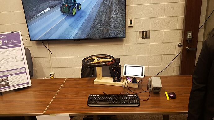
5 Likes

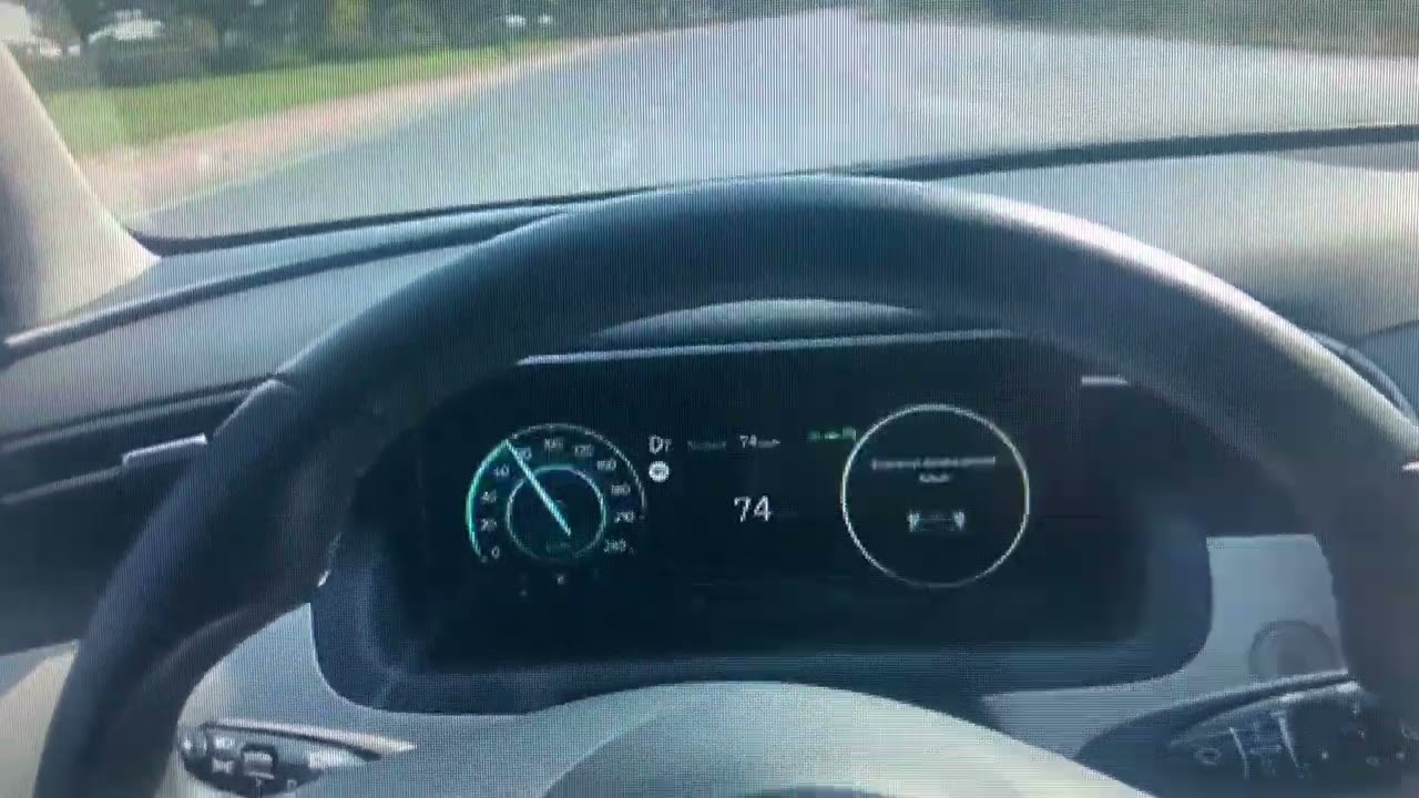
Hello, what I understood from the camera I think is the depth camera for lane tracking, is it correct? If so, I’m working on it right now, I have a ZED2 stereo camera, I’ll let you know as it progresses. You’re right about current monitoring, pins 5 and 6 on the BTS are r_is and l_is, so you can get an alarm for current while rotating in the forward and reverse direction. I recently left the steering wheel while following the lane in my own car for testing, and when the “touch the steering wheel” warning appeared on the screen, I just applied a very low force with my finger and it detected it, I’m still not sure how they do it, I think they have a very sensitive torque sensor.

1 Like

I’m glad you did well, it was clear you had taken much time and care creating and understanding it. I had fun reading it too. The internet is a magical place.

3 Likes

No, it was just an inexpensive USB web cam in a 3d printed box to keep the dust off of it. The camera had no depth perception. We filtered the image based on colour to detect the row locations. The output from the vision algorithm was the distance from the center of the row to the center of the field of vision.

Are you working on using the camera to detect rows? If so I can probably find some images of intermediate steps in our vision algorithm and describe what’s happening.

1 Like