Not the Blite. It has 2 uarts like the simplertk2b, but in xbee footprint. Yes it is just a smaller board is the only advantage.
We have an agreement with Ardusimple to do a groul buy to get a price lower than the simplertk2b. I think its 165 usd. After we test the boards we will post them on github and we will start the group buy
Hello all !
Sorry to come back with the same problem but I think my F9Ps are not configured correctly, the “no RTK” LED keeps flashing on the left board.
Can someone give me the manual configuration or a link for the txt file?
So I’m curious, how do these all-in-one boards work with the 24V motors?
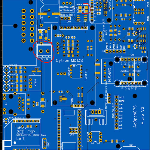
Richard added the 24v option just for the motor guys
you will solder the 24v jumper top right, and connect power to the header “24v IN”
Ahh… I see now that I actually take the time to read.
So if I’m understanding correctly, I would plug an external 24V supply into the board there.
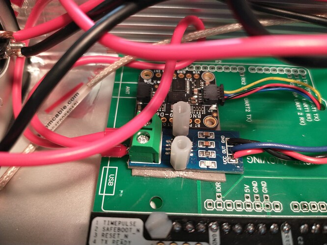
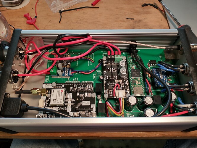
Here is the final build pictures of my dual board with a single GPS, BNO085 and ACS712. Note that I had to modify the autosteer.ino file per the following post to make the ACS712 work correctly.
https://discourse.agopengps.com/t/autosteer-disengagement-torque-measurement/1367/85
Picture of the BNO and the ACS712. I would have to use tall headers to get a second GPS installed above these.
Full board shot with in case.
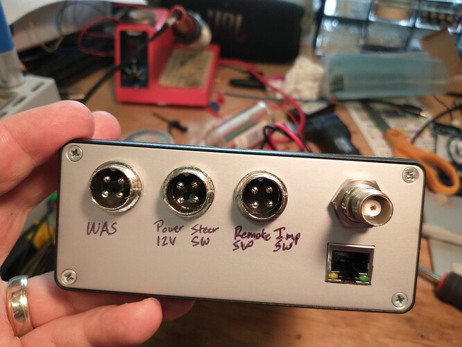
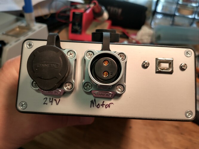
Connectors on ethernet jack end.
Connectors on the motor power end.
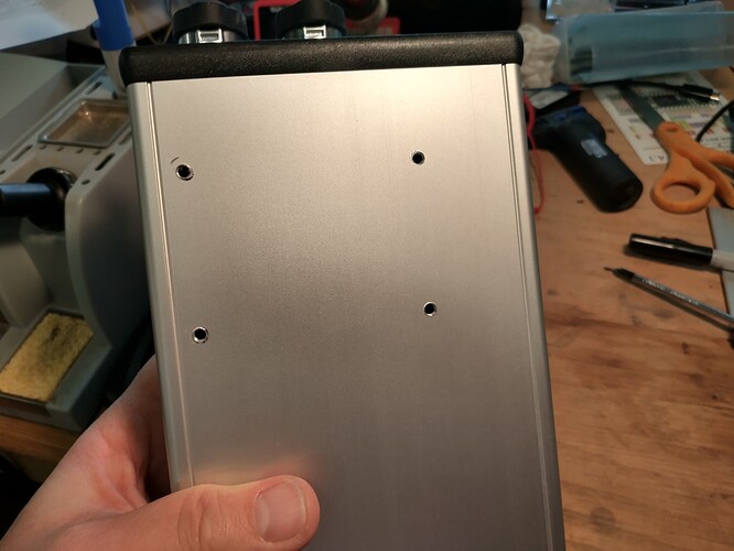
Tapped holes in the bottom to mount the 12V to 24V booster.
Thanks for the board design!
Hi Jimc; I’m confused, is this the only gps card that is all in one? So Panda? But Panda would not be a motor driver.
@whiterose I don’t know that this is the only all in one card. Based on the information I had when I started this project it appeared to me to be the only documented card with information in the actual support files download.
The basic panda board just combines GPS and IMU. Then you use a separate autosteer board.
At first blush this one appeared to do everything I wanted but it turned out there was some tinkering to make it work the way I wanted it to.
Now it does GPS, IMU, and autosteer all on the same board.
I will add a separate machine board for section control on the planters and I will add the rate controller board for the fertilizer spreader.
So, if you used a single gps card, how will you receive the correction signal (RTK)? And what ino code will you install on it? As far as I know, the all-in-one card has been released as Jhmach 2 for now, that is, with a dual GPS card.
There seems to be a lot of confusion about what PANDA is, so I will take a stab at explaiming it as I remember.
PANDA is a program sentence similar to PAOGI. It was developed by Brian to be able to cure some of the timing issues between the gps sentence and the imu sentence. He developed it to be able to take a gps reading and an imu reading at a precise timing, and fuse them for a more accurate heading, roll, and position.
The results were remarkable, so a single gps board was developed to use the teensy and the PANDA sentence to make a very usable single antenna gps with imu.
Now the new .ino incorporates both PAOGI and PANDA sentences, depending on whether you are using dual, or single with imu.
Thank you for the explanation Jhmach, although I follow very well, I can’t understand some topics due to my language, well I’m thinking of using an all-in-one card, but not dual but single, I have your double empty pcb, and from my own base station (2nd ardusimple) I get fix signal to rover by radio signal, what ino do I need to install when I make an all-in-one card like Jimc’s? I would be glad if you provide a link.
I am using the following. With the modifications as noted in the link above.
You will have to change the IP addresses in the files also.
It may be better to use the following.
The link jimc posted is good.
There will be a new release pretty soon. When it comes out be sure and update AgOpen and the .ino in the Teensy. It has a lot of fixes, and a few real nice updatea as well.
Edit.
The new all in one boards will be release in a few day as well. One is the replacement for this board and the other is the same but uses the new f9p Micro. Both can be ordered fully soldered from JLC and have the acs712 and many other features uncluding 24 volt motor option.
So, GPS is working and I have an RTK fix. Autosteer is working for that matter but there some problems. I am using an existing hydraulic valve on the tractor as the tractor came stock ready for autosteer. It has two solenoids for steering, a 3 pin pressure sensor and a solenoid activation. I have the solenoids connected to the md13s. When ever I press the test buttons on the md13s the tractor steers both ways, however, when the md13s is controlled from the teensy it will only steer to the left and never to the right. Does someone have a diagram for how to connect the pressure sensor and solenoid activation on this dual board? Could someone explain to me how this is supposed to work with the pressure sensor and solenoid activation?
On my setup i had either the motor direction or the wheel angle bacwards. I guess if the wheel angle is positive value to the right, reverse the motor direction and send it.
I have never used the pressure sensor. @Richardklasens_admin added that and maybe he will respond to help with an answer
Which board do you use?
The pressure sensor should be used as a 4-20mA sensor.
On my Setup, i connected my signal pin of the pressure sensor to A0 on the PCB, and obviously the power and gnd to the PCB. My solenoid activation valve does get activated over a relay via a external switch. You could use the 5V signal from PWM2 (which also goes to the Cytron) to activate a relay that switches on your activation solenoid. As soon as steering is active PWM2 outputs 5V.
But I wouldn’t take this as my only safety circuit, install a external switch in the supply of your relay to ensure protection even if the software/pcb fails.
You said that U10, or CNY17, is for speed pulse output, that is, it will give a slow pulse when I go slow and a fast pulse when I go fast. Can I use these pulses to change the frequency or duty cycle of my pwm nozzles? Of course, after calculating the flow rate of the blow I will use according to the nozzle I will use and making a calculation with duty accordingly.
I’m not sure how your system works. What the speed pulse does is create an open/closed circuit at a frequency based on speed. So, it is an open switch at zero speed. The Dickey John/ John Deere planter monitors read speed this way. As far as I understand.
@theGtknerd could probably explain it more accurate
Thank you, I didn’t know it was used in planter monitors.
