My results
Imu behind back seat, antena in yhe front
My results
Imu behind back seat, antena in yhe front
What do I need to change code to use the Skytraq PX1125R?
I booted and only the message appears: Swapping GPS ports…
GGA is enabled.
Also match the baud rate, teensy ino expect 460800
But if skytraq cant go that high, then set it different in ino.
Yes, it is at 115200.
My board.
Schematic_PANDA_2023-06-05.pdf (74.6 KB)
So both set at 115200.
And you have an imu (bno085) connected to the panda board also?
Maybe skytraq use opposite rx tx? Try to switch
Yes, all 115200.
IMU its ok.
Skytraq RX → Teensy TX(8_PWM_TX2_IN1)
Skytraq TX → Teensy RX(7_PWM_RX2_OUT1A)
Output Serial:
Start setup
SerialAOG, SerialRTK, SerialGPS and SerialGPS2 initialized

Starting AutoSteer...
ADC Connecton FAILED!
Autosteer disabled, GPS only mode

Starting Ethernet...
Initializing ethernet with static IP address
Ethernet cable is not connected - Who cares we will start ethernet anyway.

Ethernet status OK
IP set Manually: 192.168.5.120

Ethernet IP of module: 192.168.5.120
Ethernet sending to IP: 192.168.5.255
All data sending to port: 9999
Ethernet GPS UDP sending from port: 5120
Ethernet NTRIP UDP listening to port: 2233
Ethernet AutoSteer UDP listening to & send from port: 8888

Starting IMU...
CMPS not Connected or Found
0x4A BNO08X not Connected or Found
0x4B BNO08X Ok.

useCMPS = 0
useBNO08x = 1
Do you still get the swapping GPS ports?
And you have tried Skytraq RX to teensy RX ? (and TX to TX)
What is the device labeled U4 Single / Dual-Right? Is that socket populated? The schematic shows U1, U4 and Teensy all on the same RS-232 circuit. Normally RS-232 is 1:1. There are some diode techniques to have multiple devices but the data would be mixed since RS-232 has no concept of addresses.
Still, I haven’t tried switching ports. I am going to try.
I tried and still I got
Swapping GPS ports…
Perhaps the Skytraq is not compatible with the Panda code.
I have used the SkyTraq with the Panda code and it works fine. It looks like the problem is your schematic / board. It has 2 RS-232 devices going to the same serial port on the Teensy. That will never work. Those two devices need to be on separate serial ports.
Did you try teensy pins 28 and 29? Was thinking they are the ones for positioning and ports 7 and 8 for dual antenna setup.
The Xbee = Micro F9p. But not used. I just put it in the scheme if by chance I stop using the skytraq and buy an f9p.
The code has an auto swap. It should work using 7/8 or 28/29. Correct?
To be honest I don’t know. I tried my receiver (F9P Blite) on those pins and it worked. Will have time for checking 7/8 pins only on weekend so can comment something maybe as well.
You have to ensure, that your skytraq receive provides CGA and VTG sentences to TXD/RXD pins with 115200 Baud.
I played with the SkyTraq breakout board a bit and it is different than an F9P.
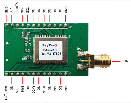
NMEA position data is transmitted (TxD) out of the board on J1 pin 8.
RTCM correction data is received (RxD) by the board on J2 pin 7.
The board does not have non-volatile memory for user supplied configuration. It loses any user defined configuration when power is lost unless there is a battery connected to J1 pin 10. A CR2032 or similar 3v lithium battery works fine.
Unfortunately I tried everything and failed. If anyone uses Skytraq PX1122R board and managed to make it work help me.
Check Out Chapter 7:
NS-HP-GN2-User-Guide.pdf (2,5 MB)
You need the right configuration, like Rover Mode Configuration 2 for using TXD as NEMA out and RXD asRTCM in. Use the GNSS Viewer to do the configuration.