CANBUS is pretty difficult to destroy. The voltages suggest all is well with it, and anyway it can recover from shorts to live or ground. If the Vbus was dead, I’m pretty sure your tractor would be screaming it from the rooftops and you’d sure know about it.
The fact a calibration worked seems to suggest it’s all good. Am wondering if they’ve set the valve on a different address or something weird like that…
If the dealer establishes a connection to the tractor with his laptop, he can see the steering angle. Unfortunately, I cannot see the steering angle on the canbus (connector x230) under the address “0CAC1C13”. at “0CAC1C13” I can see the current status of the valve. when I send “0CAD1C13”, the tractor steers to 0°, regardless of the position of the wheels beforehand. but I cannot steer to the left or right
Does anyone have any ideas what I could try?
As I understand it, the sensor can be found on the Canbus, but at a different address - is that possible?
Hello, i have a Deutz 6185 TTV not steer ready. I want to know if it would be possible to read the WAS via the canbus. Is this possible with a standard Aio4.1 board?
You wont need to read the was via canbus if you cant steer it over canbus. You could find the was connector and use that and wire direct to the ampseal. This is possible with massey and nh so could work on yours
If it turns and set to 0deg, it means that everything works, you’re just sending the wrong control curve or the steering angle sensor is damaged or incorrectly programmed into PVED. I’m betting on the wrong curve.
Do a test, send the following frames:
left: 0x80 0x7B 0xFD 0xFF 0xFF 0xFF 0xFF 0xFF
right: 0x80 0x7F 0xFD … the rest the same
straight: 0x80 0x7D 0xFD …
The same address that worked for you before.
According to this address 0CAD1C13 and my knowledge it looks like a CLAAS tractor to me, or massey i think.
edit: I watched your video, I see that it steers but it is definitely not good that byte1 and byte2 are constant. I do not understand this, either this tensy is lying or you have something damaged with the steering sensor. But in that case how would it steer at zero deg. I do not understand this, I steer tractors of different brands, I have made about 40 of them, but I have never had anything like this.
thats the thing im wondering about because the Can sniffer says that these two bytes are constant but the laptop from my dealer sees the sensor’s value correct.
we’ve changed the sensor a year ago becaus it wasnt working correct (all wheel drive wasnt disengaging correct in auto mode) but this change nothing on the canbus…
hello, do you have done steering with the orbitrol pved steering valve with the canbus? on Valtra T4 with smarttouch? And i’m also looking for the adres to use the " activation button" on the smarttouch. We tried to steer but the tractor gives a error code. We want to activate the Valtraguide GPS from on the harvesting machine.
Good evening, I dont really know anything about coding, but I run a John Deere 4640 screen in a massey 8737S tractor for controlling the planter and mapping the data for use in operation centre and in our John Deere combine.
I run it as a third party screen so it uses the signal from the trimble receiver, now according to my local mechanics its not possible for the deere screen to communicate with the tractors steering controller because the deere uses different CAN than die MF.
The problem comes in on the headlands the "planter"s location on screen jumps around with sudden stops or direction changes, not a big enough deal for me to buy a bridge and just go deere screen and receiver all the way, but I keep thinking that it should be possible to have the JD see the controller of the MF. That would solve the jumping problem but I think in theory it should allow you to run the autosteer through the JD also with the signal from the trimble receiver.
But I don’t know anything really about CAN so was just looking for non-dealer bound answers!
Hello, I’m trying in a MF 8740 ( without S), does anybody know where the can bus connector is? I have search in the right side of the seat, but I haven’t seen any x230 connector. I have connected to the two isobus diagnostic connectors , and in one of them I have read the WAS angle, but under the 0x0cacfff0 , it is said, it is a broadcast from f0 to the world.
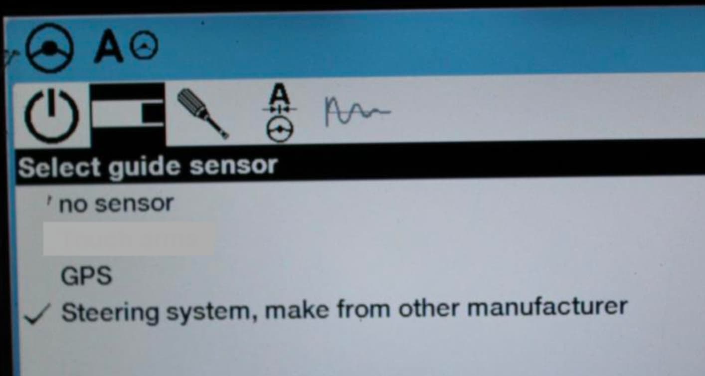
Hello, again , I have seen in agra-gps that it is needed to activate the option of the photo, Is it needed? The tractor I’m trying to test has not this option.
I was testing with arduino project, In the tractor I’m testing, Axion 830 from 2020 ( A60 in serial number) I don’t have the third option in Cebis, only the first two. If i select no sensor, am i’m using the 1B address for navigation controller, wheels move but at the end appears an error, may be because of conflict between my arduino and the navigation controller of the tractor… If i select GPS, cebis directly says: GPS is not available and nothing happens. If i change with the serviceTool program funcion the address to 1E, it is stablished by the tractor, then sends the ac1e13 codes correctly, but nothings happens with the wheels. So all indicates that i have to do the bridge that you commented, but, question is : Can I avoid bridge putting the third option “Steering system, make from other manufacturer” ? Has this option an unlock and it is needed pay for it? And a third question is, ok, ill do the bridge, has to be the atp disconnected from tractor hasrness ? like seems to indicate this photo?
The option for other manufacture is a unlock that costs and is for a specific brand like agragps or trimble etc. To use this unlock there is some sort of crc in one byte that we haven’t worked out and none of use want to get an iso manufacturer ID and pay claas for each tractor they generate a code for. So we came up with a hack where we change the address in the pved and send the AD message directly to the pved and receive the AC from pved.
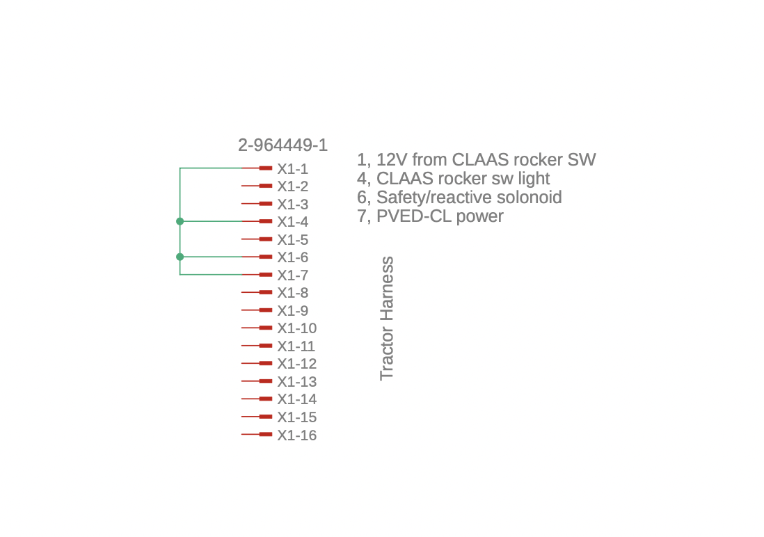
On you tractor you will need to make a bit more than a bridge plug as the WAS signal needs to get to the atp module so it can send the was signal to the pved valve via can. If you don’t make this bridge correctly then you will get error codes.
I made this diagram for connecting an AIO board, you should get an idea from it how to make a harness to go between the atp and the tractor harness. AIO4.1 CLAAS SR tractor without relay.pdf (22.5 KB)