Pat
I’m trying to get OG3d to work on a 600’x600’ slab base sloped 2 directions. Would it work to survey the 4 corners and use that as a design. I don’t really need the cut/ fill data.
I would say it can be easier with opengrade. It will follow the design up to 1000’
Slope in 2 directions 90 degree apart? You could drive the combined angle direction then draw the slope.
OG3D is designed to use a grid of pts. the distance is hard-coded, I think max distance between pts is about 60 fts.
It would only work if the 4 point are aligned north-south, east-west and the value in the source code is changed to make averages from pts much farther away.
The other way with OG3D would be to drive the contour a use a third party software.
I’m using pcb v2 to run my on off valve from my old laser system. When I got it connected the ma or mb light is on (depending which Arduino I’m using) on the cytron is on all the time till I switch the autoblade on. Tried different cytron , pcb board and a few different arduinos and still does the same thing. Any ideas what I could try?
If you are using my version of Opengrade I just updated the ino to github.
the last one is 2022-04 for OG3D v1.1.xx and OG v2.2.xx, there are always some mess up with Github
You have to change some Bool in the ino code depending what options you use
I used it some time ago with a pcb v2 and worked as expected
If you still have trouble, please specify which version of which software you use.
I got it working. Had not turned [manualMovePropLever] off. Thanks for your help
1 Like
This is a fantastic project and I’ve been reading through the various posts, but I do have a few questions to set up my own system.
I’m looking to add automatic control to a Ditch Witch ride on chain trencher so that I can install some short runs of land drainage on the farm. The depth control on this uses an open-centred hydraulic system to control a ram that changes the pitch of the boom. The plan is to get an open-centred valve, plumb in the P and T and then tee into the lines that go to the ram from the manual depth control valve.
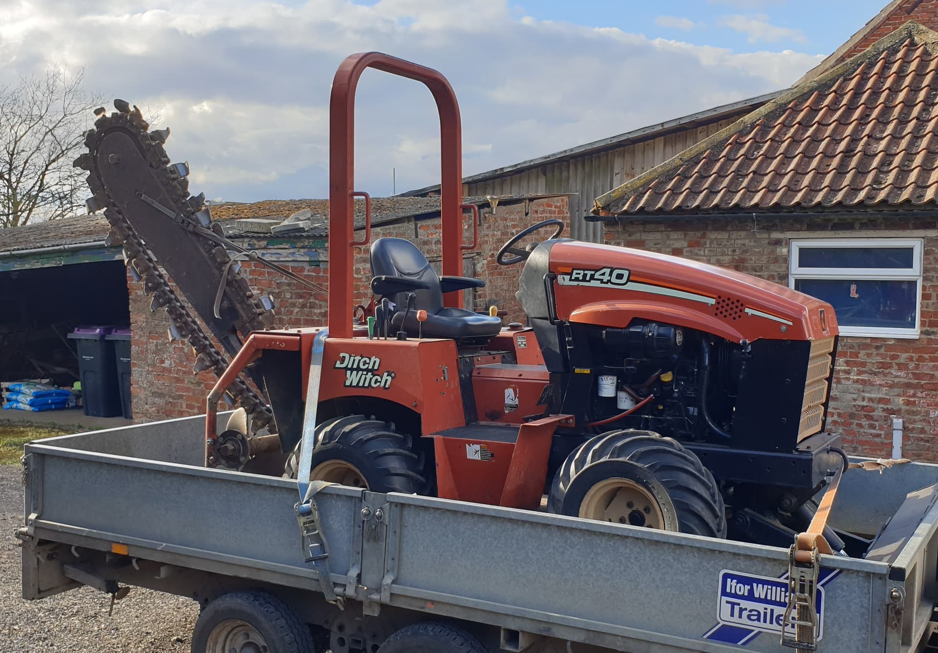
GPS information will be provided by a Reach RTK module mounted on a frame over the centre of the rear roller of the chain (some fancy linkage is involved to give linear height variation), which can output corrected position via TCP. This will be fed via a virtual serial port into the software, the same as I use for AgOpenGPS. The plan is to mount the GPS to the ROPS bar for the survey (effectively over the rear wheel to follow contours accurately) then to move to the antenna to over the boom for trenching.
-
OpenGrade version - which is the best version of OpenGrade to use? Pat’s or BlackAce’s? It has gotten a little overwhelming reading through trying to track which is the latest and/or best for laying pipes
-
Suitable valve - can anyone suggest which valve to buy? A lot of the links on here seem to have expired and I’m looking for a straight-forward all-in one solution.
Thanks!
I can say that mine is USB only and you have to manually draw the reference line (no auto-draw) but it should work fine, it follow nicely the desired height.
I guess you are going pretty slowly with this? So I would say a on-off valve should work, just put flow control to reduce the speed, it should be able to follow without overshooting.
I use a hydraforce proportional valve with a priority valve to from an OC circuit.
Something like this:
https://www.princessauto.com/en/12v-dc-tandem-centre-do3-directional-control-valve/product/PA0008512436
https://www.princessauto.com/en/1-station-d03-valve-subplate/product/PA0008163453
1 Like
Can anyone tell me if this schematic is still good and current? One thing I’m curious about is why the one DAC has to A0 pin pulled HIGH.
Also
-in the latest code on github I can’t find the buttons in the INO’s.
-there is UDP included in the code is this still running on an ESP32 or a Teensy
-if UDP on ESP32 which pins are used to communicate with the NIC
pat I have a bit of time so I’m getting back on this project. Do the points need to align perfectly and be the same distance apart?
Does this ino work for open grade too or just the opengrade3d version?
It should work with both. They use the same communication protocol.
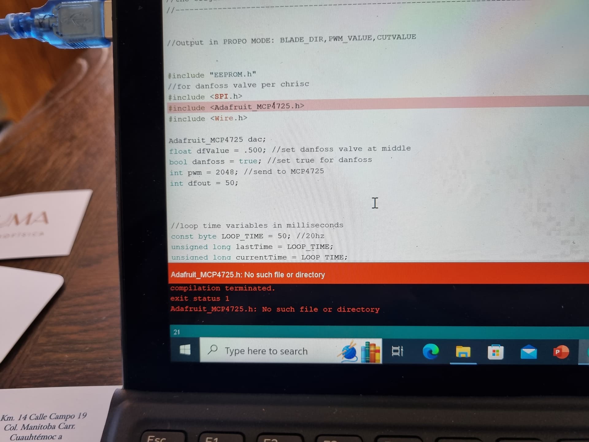
Hey im trying to upload the code on an arduino nano and it doesnt work. This code appears. What should i do?
Probably have to install the Adafruit MCP4725 library
Bonjour,
Je me pose quelque question sur la faisabilité d’intégrer au programme une fonction de de control d’effort en se servant du tôt du patinage réglable par un potentiomètre ?
Merci
Quentin
Has anyone any idea what i could do that the valves would react sooner to correct in open grade? I used the ino from chris and the john deere svc system and i did some tests today and it reacts after -2 cm and after +2 cm give or take but nothing happens in between. Is this precise enough to use open grade on fields or is there something I could do to get it closer?
It’s that just the amount of dead band the scv/hydraulics have? Try adjusting the value that it’s outputting to the scv control, like minPWM for autosteer.
What is your deadband setting in the OG valve setting page? Should be 2 mm by default.
You make my think it would be cool to read the tractor CANbus to read the engine load and transmission speed.
Would be really nice to have the blade lifting automatically if the engine is overloaded or tractor spinning.
I now have a tractor with CANbus, I will see if I have time to play with that.
How would you read the slipping?
1 Like
Ive tried 1 mm and 2 and 20. I dont notice a lot of difference.
I had the pwm on 30 min and 60 min but somehow i got the best results if i had min and max on 180 and just put the pressure as low as possible.
1 Like
Je me suis renseigné auprès de mon concessionnaire Fendt on pourrais récupérer la vitesse boîte sur la prise outil 7 plots de notre tracteur et la vitesse GPS sur la prise RS32.
Il resterais donc à créer un code afin de gérer ce tot de patinage qui à mon avis doit être réglable via un potentiomètre ( 0% de patinage toléré —> 100% de patinage toléré) un peux comme mon système commercial au laser mais celui si se fait via une cheville capteur de force sur l’attelage mais cela ne fonctionne pas bien !
J’attend les retour de mon mécano pour connaître les broches exactes sur lesquels récupérer ces infos vitesse
Merci de votre réponse Patrick