He’s prone to not respond for a few months at a time. As was the case last spring.
Hello, please send me mail, grbaraki@gmail.com
Thanks. Mail sent a few minutes ago from address seam.armancourt@free.fr
Has anyone had any issues with the 5v pressure sensor? I can’t get no lower voltage even without pressure. Have good earth and wired in as it should be according to the forums.
What board you using?
4.5 standard. I’ve managed to get it working with a potentiometer just not the sensor
Okay than the board is configured properly. I remember when Ive been installing the valve, you receive terminals and connector separetly. Did you insert them all the way into the connector, maybe its not making contact? Is it LS or OC valve? There are 2 types of sensors…
It’s an open centre type valve. Double checked the wiring just in case. Have continuity between earth pin and the junction box
I recommend checking the connection and cables several times.
It happened that the sensors had a manufacturing defect.
1 Like
When looking for s steering valve, what flow rate should I be looking for? It’s for a JD 7600 tractor
Hello, I am new to all of this and after much reading, I decided to dive in. I just got the PCB All In One V4.5 Micro and the Baraki hyd. valve I ordered from Navisklep in Poland (I live in Iowa). I am assembling my own wire loom to connect everything, and I have a few questions for anyone who would be so kind to help. I am connecting all the wiring through the AMPseal connector. The hyd. valve has the sensor on it to shut off the autosteer when the steering wheel is moved (just like in the pic from Flatfarmer); from what I can tell the AMP pin #10 should be wired to sensor pin #1, the AMP pin #1 (5v) to sensor pin #3, the AMP pin #4 (ground) to sensor pin #2. Is this correct?
I have a ride height sensor for a Land Rover that I’m using for a WAS. So I’m planning to use the same AMP pin #1 & AMP pin #4 for power and ground that I’m using for the sensor above. Should work, right? And I’m really not sure where to connect the blue signal wire, #2 or #3? Thanks.
Here’s the pin out list and drawing in case you need it.
I’d use Amp pin 2 for was signal
Dont use was gnd pin for anything else but the was. Its not working well! Use another gnd
Thanks for the feedback. I will use your suggestions for the connections. Another question is whether or not to use relays to control the electromagnets on the hyd. valve. I am guessing it would be too much of a load to directly connect the PCB to it. I don’t want to fry my new components. But I also don’t want to over complicate things with extra relays if they’re not needed.
Also, when I mount the 4.5 micro PCB in the cab, I’m guessing it needs to be level and oriented a certain direction for the IMU to work right? And maybe mounted near the roof rather than on the floor? Thanks.
Location or hight doesnt matter, orientation does.
Left and right pins dont need relays, I dont think this is even possible because its pwm signal… lock pin has a mosfet which in teory should be enough but people reported it smoking so we use relay only for lock pin
You can configure the bno X or Y -orientation in AOG (Auto Steering Configuration). Better install it on the floor rather then near the roof.
1 Like
I’m not sure which way to orient the micro PCB when I mount it, and it apparently matters. The front face of the box has the AMP seal connector, the RJ45 connector, the connector for the antenna, plus diode windows, lettering and such. This front face is 6 5/8" wide. The sides of the box measure 4 5/8". If I mounted the PCB between me and the windshield, when I am sitting in the seat driving the tractor, do I want the front face looking directly back at me, or facing 90 degrees off to one side or the other? Thanks
both directions are availiable, set either X or Y - orientation in AOG Dialog “Auto Steering Configuration”
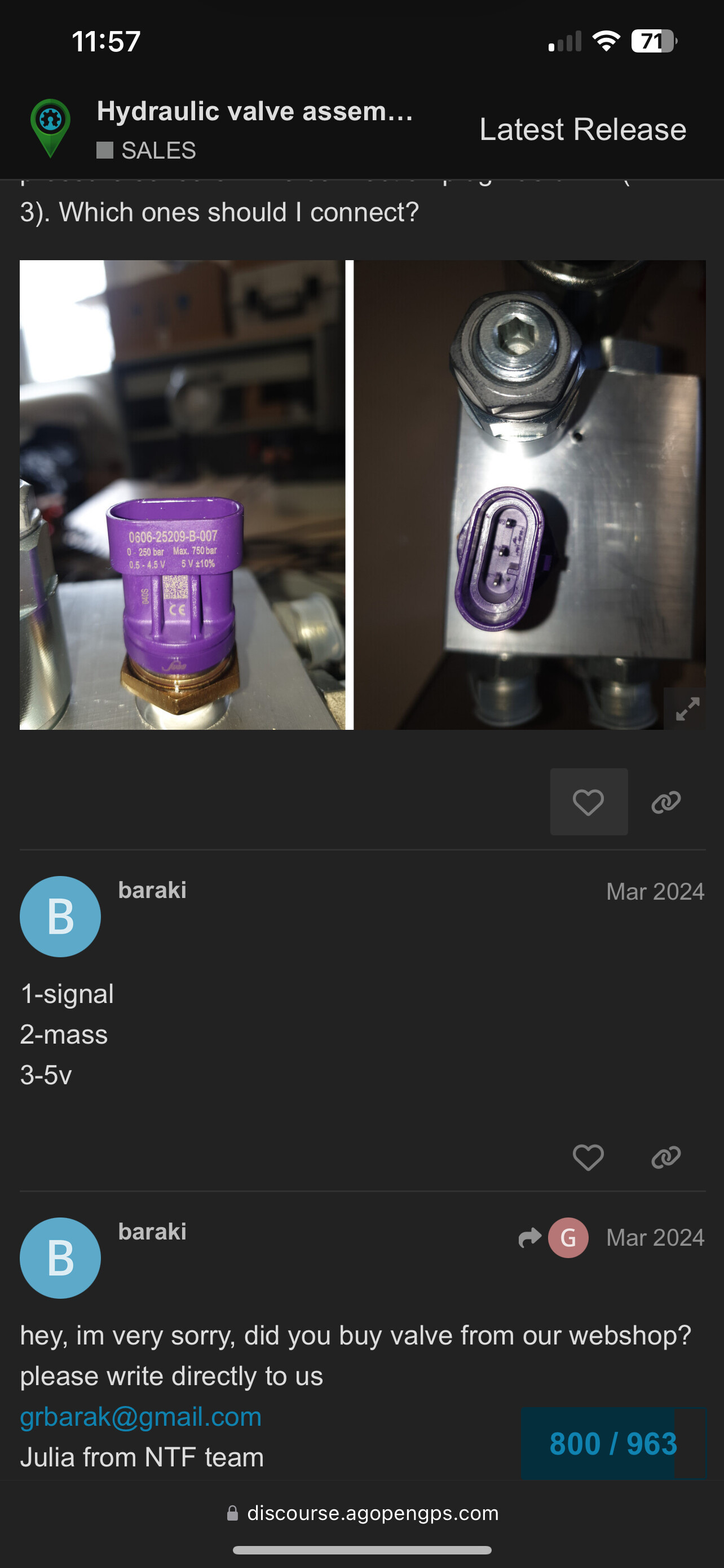
Is there a diagram somewhere that shows how to connect a 3 wire pressure sensor from baraki valve to a pcbv2?
I guess, connect
1 Signal to A0
2 GND to GND
3 5V to 5V