Panda - ADC Connecton FAILED!

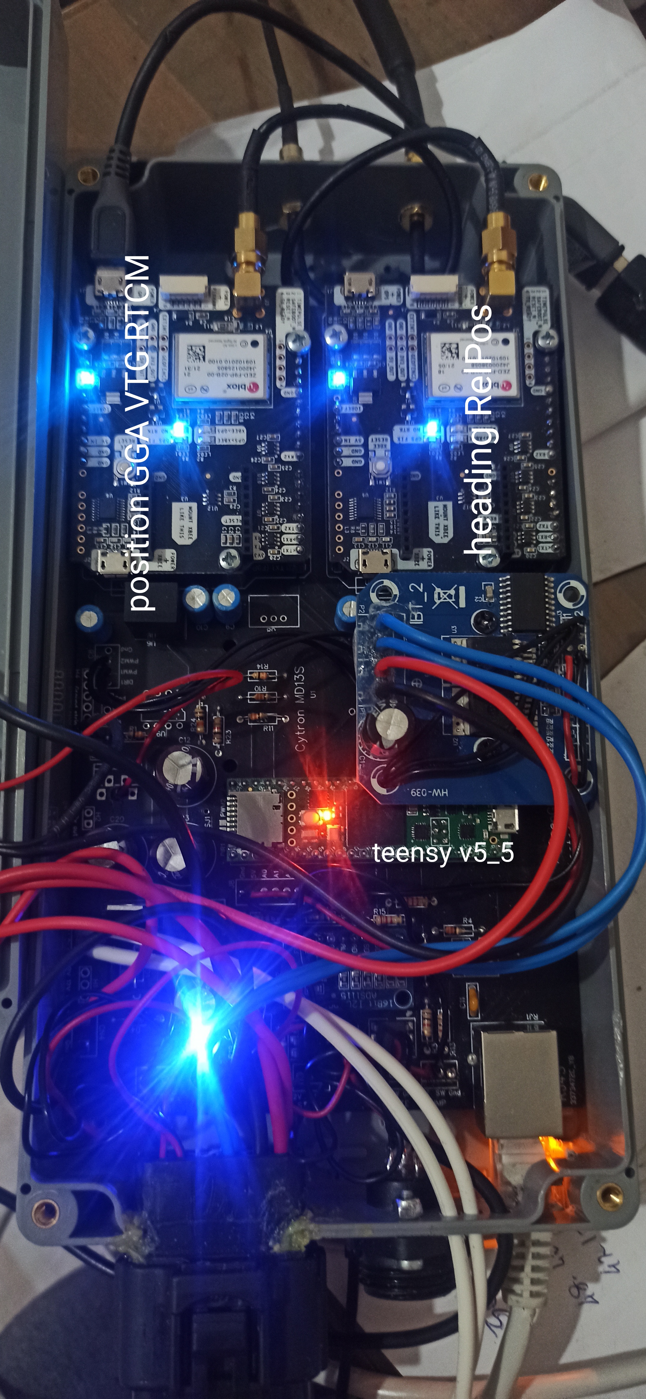
I’m using a ZED-F9P SMA from Sparkfun.

When I started up after dinner I was back to Swaping ports.

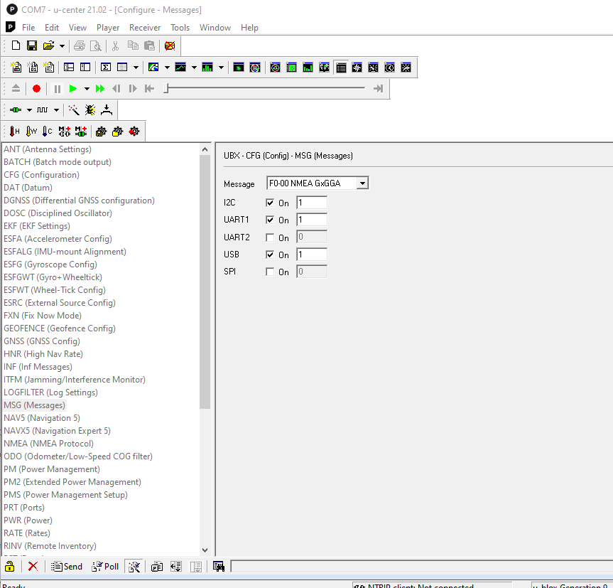
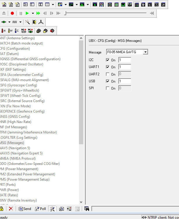
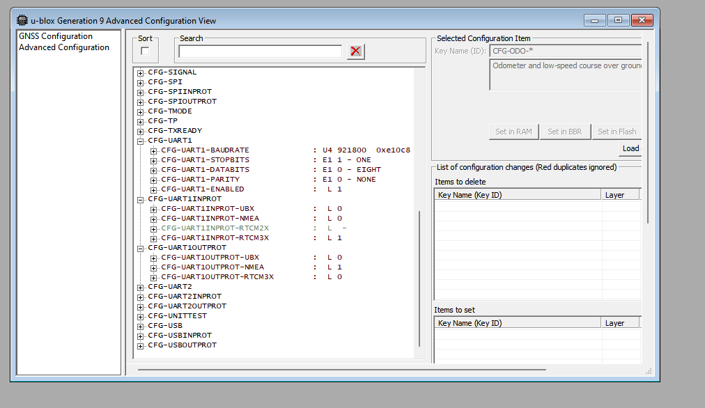
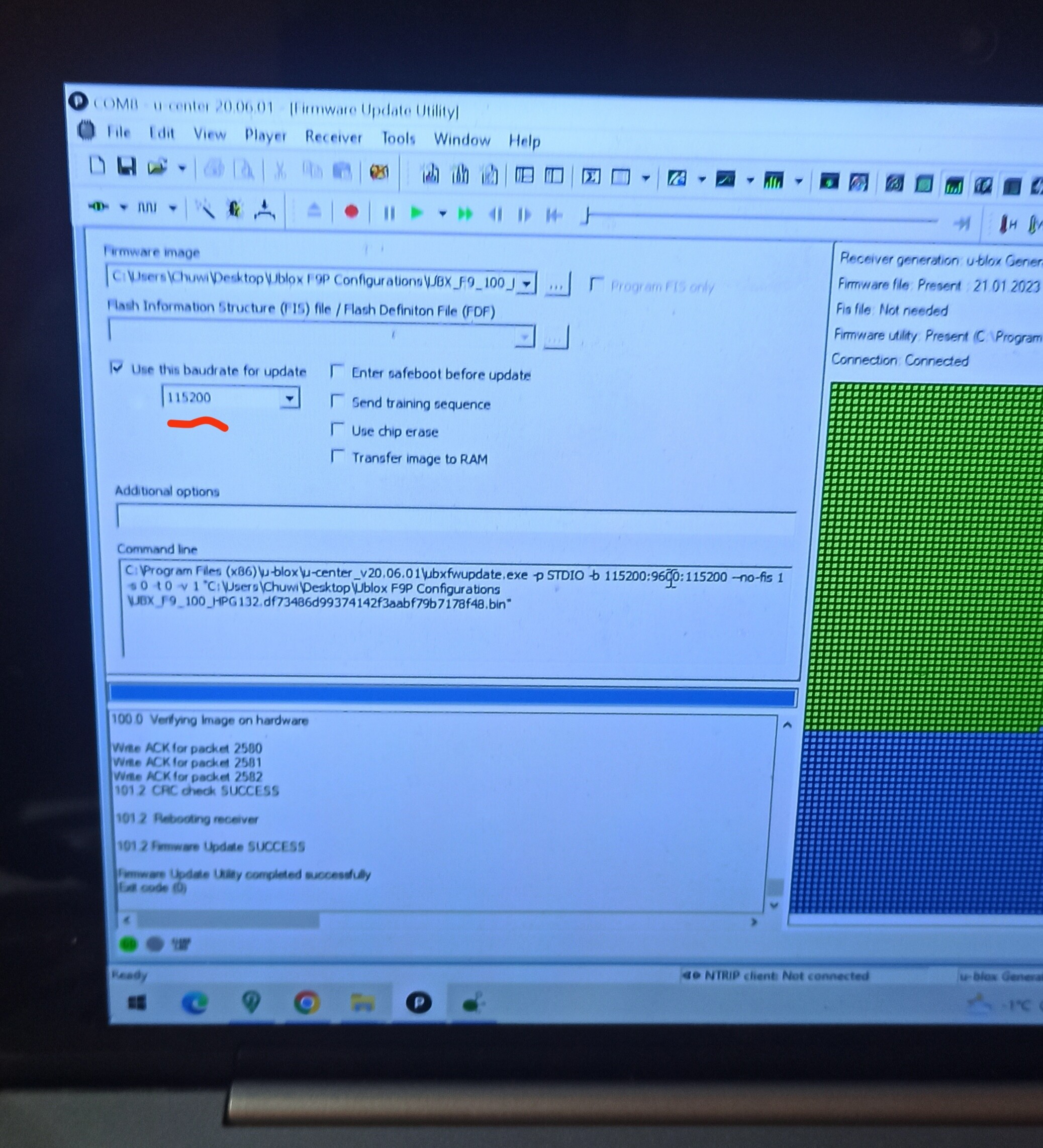
I redid the firmware 1.32 and the config file as in the above post. This time I did as suggested in the link you just posted and disabled everything but GGA and VTG. Here is what is coming out in Ucenter. (I unplugged it and plugged it back in to make sure it stuck.)

20:11:52 R → NMEA GNVTG, Size 21, ‘Course Over Ground and Ground Speed’
20:11:52 R → NMEA GNGGA, Size 42, ‘Global Positioning System Fix Data’
20:11:52 R → NMEA GNVTG, Size 21, ‘Course Over Ground and Ground Speed’
20:11:52 R → NMEA GNGGA, Size 42, ‘Global Positioning System Fix Data’
20:11:52 R → NMEA GNVTG, Size 21, ‘Course Over Ground and Ground Speed’
20:11:52 R → NMEA GNGGA, Size 42, ‘Global Positioning System Fix Data’
20:11:52 R → NMEA GNVTG, Size 21, ‘Course Over Ground and Ground Speed’
20:11:53 R → NMEA GNGGA, Size 42, ‘Global Positioning System Fix Data’
20:11:53 R → NMEA GNVTG, Size 21, ‘Course Over Ground and Ground Speed’
20:11:53 R → NMEA GNGGA, Size 42, ‘Global Positioning System Fix Data’
Start setup
SerialAOG, SerialRTK, SerialGPS and SerialGPS2 initialized

Here is where I am (again) from the serial monitor.

Starting AutoSteer…
ADC Connecton FAILED!
Autosteer disabled, GPS only mode

Starting Ethernet…
Initializing ethernet with static IP address
Ethernet cable is not connected - Who cares we will start ethernet anyway.

Ethernet status OK
IP set Manually: 192.168.1.120

Ethernet IP of module: 192.168.1.120
Ethernet sending to IP: 192.168.1.255
All data sending to port: 9999
Ethernet GPS UDP sending from port: 5120
Ethernet NTRIP UDP listening to port: 2233
Ethernet AutoSteer UDP listening to & send from port: 8888

Starting IMU…
Swapping GPS ports…

Swapping GPS ports…

I unplug the 5V to the teensy when I plug in the USB (if that makes a diff)

From your first post, you are trying to use PANDA + V2 board?

So first we just want to make PANDA, try swapping your rx tx wires from the Sparkfun to the teensy. Ensure the baudrate is set the same inside the sparkfun and in the teensy. Uart 1 is the mosi/miso on the sparkfun.
make sure the “dsel” jumper on the back is not soldered shut.

If the teensy is making panda it will blink, Panda will leave on the teensy Ethernet connection. The Green data light on the Ethernet port will blink fast and continuous if PANDA is being sent.

If you are using V2 as the input for the WAS, the teensy will always say ADC connection failure because it is not there. The serial debuggers only work on the local device they are directly connected to.

Triple check that all of your devices IP’s are on the same network, and do not have a duplicate last number.

Be sure to send it to Uart1 also, not only USB

I[quote=“Pat, post:24, topic:11024, full:true”]

Be sure to send it to Uart1 also, not only USB
[/quote]

It has passed 24 ,so Happy New year :slight_smile:
used f9p firmware 1.13 with config 1 13.
Had no issue connecting to teensy .
When uploading firmware or config, make sure baud is quite high. Above 115000.
I am not sure 1.32 is an advantage for agopen.
1.13 has 10 Hz which is quite sufficient for autosteer. 1 32 can go higher as far as I know.

1 Like

Swapping GPS ports mean you have now communication between Teensy and your Sparkfun receiver!
I had to swap the RX/TX wires on my C099 regarding to the original Panda board schematic. It’s important to have the same baudrates on each side.

Yes that is right.

Swapping RX and TX has no effect. and I’m hooked to pins 7 & 8 - RX2 - TX2.

I figure I should be configured as described in the Sketch.

// Configuration of receiver
// Position F9P
// CFG-RATE-MEAS - 100 ms -> 10 Hz
// CFG-UART1-BAUDRATE 115200
// Serial 1 In - RTCM (Correction Data from AOG)
// Serial 1 Out - NMEA GGA
// CFG-UART2-BAUDRATE 460800
// Serial 2 Out - RTCM 1074,1084,1094,1230,4072.0 (Correction data for Heading F9P, Moving Base)  
// 1124 is not needed (China’s BeiDou system) - Save F9P brain power

Here is what I have


The RTCM messages are greyed out & I haven’t figured out how to select them. I’m Also not sure of how to set -

Serial 1 In - RTCM (Correction Data from AOG)
Serial 1 Out - - NMEA GGA

1 Like

Make sure the baudrate set for gps port in teensy ino is the same as uart1 baudrate on f9p. If these two settings dont match, my experience is you will be stuck wit «switching gps ports»

Check:

UART1 must be checked!

In my case must using Baudrate 460800 because of the internal need of the C099 board, also I don’t use UART2

image

1 Like

@wland I have set my config as you have shown above. I get connected and AGIO shows panda connected but I still have no GPS. I have swapped wires on pins on both UART1 and UART2 (on the f9) - no change. I also did continuity test from pins on teensy to pins on GPS to rule out bad wires.

@PotatoFarmer Could you share your config file? You have your Sparkfun f9 working so maybe it would make mine work also.

Just for my understanding, you tried for sure:

Teensy Pin 7 RX2 to F9P RX/MOSI
Teensy Pin 8 TX2 to F9P TX/MISO

and cross both wires

Teensy Pin 7 RX2 to F9P TX/MISO
Teensy Pin 8 TX2 to F9P RX/MOSI

with setting the baudrate 115200 for UART1 on Teensy and F9P side

Note: Be sure the DSEL jumper on the rear of the board is open.

1 Like

So you get the $PANDA message received in AgIO but just unpopulated?

Here is my sparkfun 1.32 config file, but I do not use Glonass, and uart1 I have set to 921800 because its used in an all UDP setup with a ttl adapter.

AgOpenGps Sparkfun UDP PANDA v1.txt (25.0 KB)


the config for these is a bit of a beast, it needs the port, message type and message to be enabled one by one. This is the gen9 configuration view I find it easier to use.

I am so glad you raised the question. In all my switching around I had put the wires on the X2 pins and not the MOSI. I now have Panda sentences with serial monitor. Orange light on teensy is flashing, that’s a first for that!!!

I have a green light on the antenna in AGIO, which I have not had until now and I have a GPS signal and tilt in AOG. :smiling_face_with_three_hearts: :+1:

THANK YOU ALL!!!

3 Likes

I was updating from 1.13 to 1.32, teensy wasn’t seeing it, I made the configuration as the ray_jorgensen suggested. it works perfectly now. The only problem I don’t understand is that I did the speed this way while updating, I wasn’t sure if I did it right.

The speed of the update process itself depends on this.

I updated from 1.13 to 1.32. everything was working. I updated from teeny v5_6 to v5_5. as the most recent code published. agopen not seeing GPS after teensy update. Where could I have made a mistake?

I set uart1 115.200 uart2 460800 on right and left.
Position GGA VTG 12C aktive

If you’re connected to u center, try disconnecting and then retry AOG.

1 Like

Set Uart1 as 460,800 and Uart2 as 115,200.

1 Like

I set it as you said. teensy yellow light turned off. Teensy doesn’t see it.

I turned it on and off many times and checked the ip addresses. nothing changed.

If you’re sure you saved the Config files and baudrate changes, try reloading the Teensy firmware, I’ve had numerous occasions I’ve had to do it more than once for it to work correctly.

1 Like

I updated to teensy V5.6 problem solved. Thank you for your help