So I really didn’t want to create a new thread for this but I’m confused. I’ve got the PCB v4.3STD I believe(Labeled 4.2?), as well as all of the components. I’m having a little trouble understanding the wiki on assembly. Would anyone be able to provide a step by step assembly guide? Also is there a thread on testing connections once everything is connected? I remember there being one but not able to find it. What has everyone else done for bench testing without a power supply available? Thanks!
Following this guide from the top
I’ve got a little bit of an off topic question for you. I’m not fully understanding the wiring diagram on the wiki. Especially when it comes to the wires that look like they “y” off of each other. Do you have any pictures of your wiring harness? I’ve got wire, switches, plugs, etc, so I’m ready to make it. Thanks!
No i haven’t got any pictures. The black ones are all earths so they can go to any of the earth pins.
The red power cables are just powering the board. I never fitted a relay on the power side. Only relay i fitted was for the cytron freewheel mod.
I did use plenty of fuses though as i had some white smoke on an earlier wire up.
The diagram does look more complicated that it actually is.
Just use some block connectors to start with until your happy and theyre easier to do and plsy about with, once your happy do a proper soldier joint
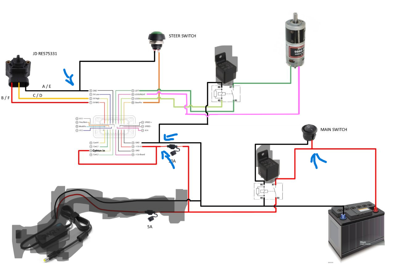
For example if you use the ampseal plug that is prewired you would take the wire that comes from pin 4 of the plug and hook it to the ground wire for the WAS and the ground wire for the steer switch. Or take the wire from the fuse holder and wire it to the ampseal plug wires to 12v in and the cytron in (if you are using a 12v motor). Like del_boy says it looks more complicated than it actually is.
So how does wiring work on a 3 wire steer switch?
Its alot easier to use a push button momentary switch. I used the wrong switch and ended up with some white smoke
What kind of three wire switch? Pushbutton or toggle? What do the three wires do?
This is how wiring diagrans are made. Your first blue arrow (close to the battery) point at a Y which could be done with two parallel red lines all the way to the battery. But drawing all those parallel lines would clutter the drawing.
Also quick question, do you have any idea what the wiring diagram is for the RQH100030? Also there is a 5v Low for the WAS is that needed for this WAS? Thanks!
No. You don’t need the 5v low. Otherwise there is just 3 wires. Power, ground, and signal. The plugs I’ve seen are red positive, yellow(or black) ground, blue signal.
?v=4GPAt9eeeNA&pp=ygUNQWdvcGVuZ3BzIHdhcw
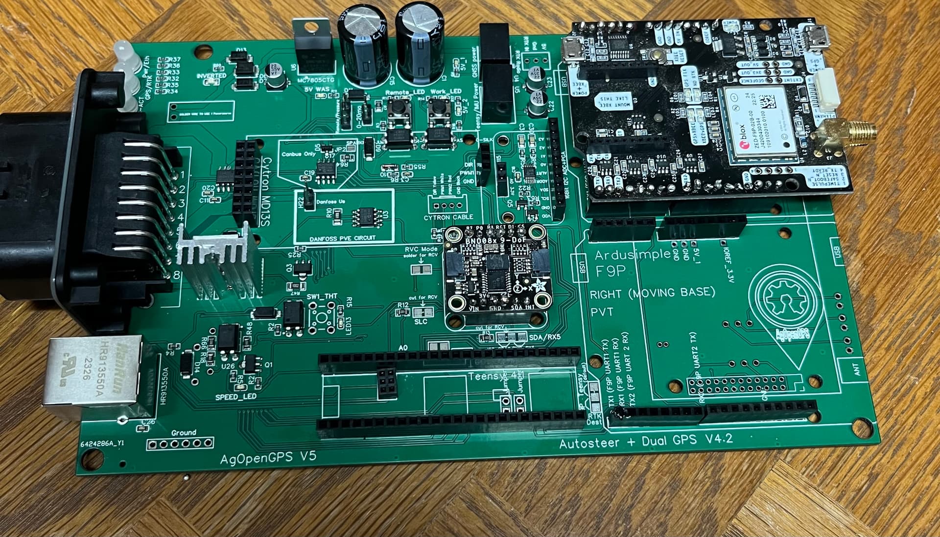
Is there anywhere that shows how to put together the whole board? I’ve got the BNO on, as well as the F9p, and I’ve just got to put on the teensy and the cytron. I’m not sure how the cytron goes on tho. Do you have to solder the wires from the cytron to the board? Thanks!
Is there anywhere that shows how to put together the whole board? I’ve got the BNO on, as well as the F9p, and I’ve just got to put on the teensy and the cytron. I’m not sure how the cytron goes on tho. Do you have to solder the wires from the cytron to the board? Thanks!
can you post a photo of the PCB which you have ?
IMU and GPS is ok
the question is what configuration files are uploaded to the GPS
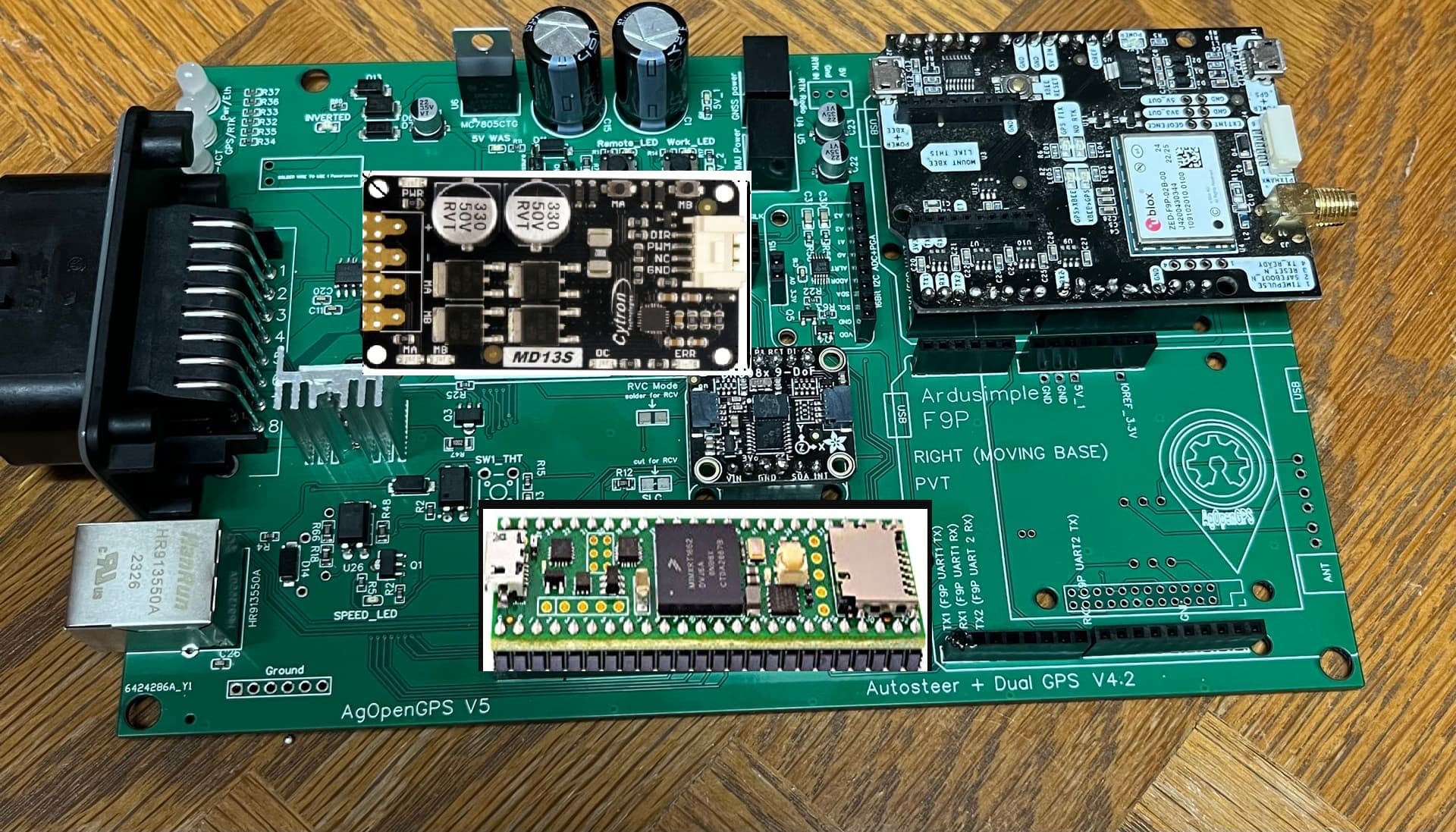
try to solder the pins to the citron well
I used the auto config in the wiki and it seemed to work.
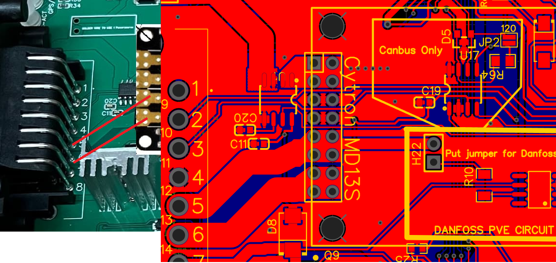
I’ve already got the pins soldered to the cytron. I just need info on the wires coming out of it. Do they go into the slot saying “cytron cable” and then soldered from the back of the board?
I haven’t connected the citron in my set yet and I haven’t done auto steering with an electric motor, but as far as I know the pins responsible for the citron in the socket you have soldered are 5 and 6 they are already an output directly connected from the plug to the electric motor unless it is to be switched on via a Bosch relay as in the diagram above, then the motor connection is slightly different
It’s better if someone confirms what I wrote and don’t forget about electrical protection
When youve got your cytron offer of up to the pcb lining the headers up and it will make more sense where to solder the pins on the cytron
If you’ve got header pins already attached to the teensy just slot it in place but looking at your photo the block of 6 ethernet pins look like they been attached on the wonk abit so might need to be careful when trying to line it all up