I built the RC12 rate controller designed by SK21. I just put together the switch box to use with it. (I didn’t have the switch box pcb made up. I used an arduino development board and followed the schematic) I put the latest switch box firmware on the nano. I confirmed the address used in the nano firmware was 192.168.5.50. The Ethernet shield lights up like it’s communicating as does the port on the Ethernet switch. I swapped Ethernet shields with the rate controller, no change. Do I need to make changes in the rate control app to allow usage with the switch box? Might there be another issue I am over looking?
There was an error in the switchbox code. It wasn’t saving any settings. There is a new version of the firmware on PCBsetup. The IP should end in .188.
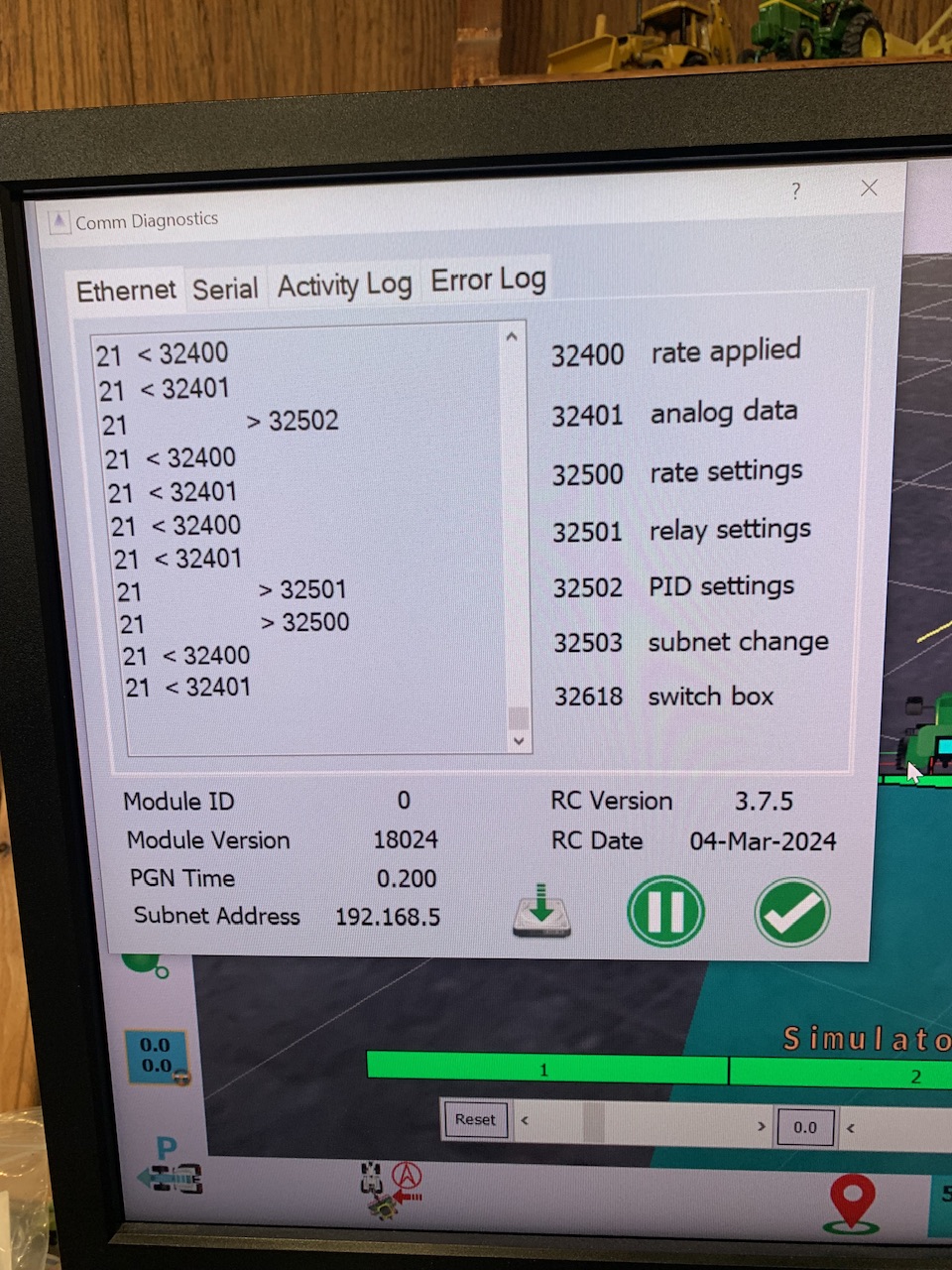
Thank you, I downloaded the new pcb set up app you linked and installed the switch box file in the nano. It is still not working unfortunately. I pulled up the UDP monitor with in the rate control app. I looked through pgn list and I do not see any 32618 pgn’s sent from the switch box.
When you uploaded the new firmware did you update the subnet with PCBsetup? It can also be done in the rate app.
I did not do anything with the subnet. I just downloaded the pcb set up, connected and hit load. How would I do that with either the pcb set up app or with the rate control app? I though about hitting send subnet under modules in the app, but I was afraid I would assign the switch box the same subnet as the rate control nano
On the modules page in rate app you can send the subnet for both. It only sends the first 3 parts of the ip (ex: 192.168.5). The last part of the ip is specific to the ino type. For a rate module it is 50 + the module ID. If the module ID is 0 the ip would be 192.168.5.50. For the switchbox it is 188 + the module ID. If the module ID is 0 the ip would be 192.168.5.188.
Thank you once again. I sent the subnet and now it is working perfectly. Hopefully next week I can get it off the bench and on to the sprayer
1 Like
I have the rate control mounted in the tractor. I am trying to run it. I have been messing with it for several hours now. Everything turns on and looks good. It connects right away. The issue I have is a second or two after I turn on a boom section the gear on the rate control app turns orange and I loose connection. I suspected the boom sections turning on was causing a dip in voltage. I ran a separate power supply wire from the power distribution terminal in the cab to the control board, so it is on it’s own power feed. Any ideas??
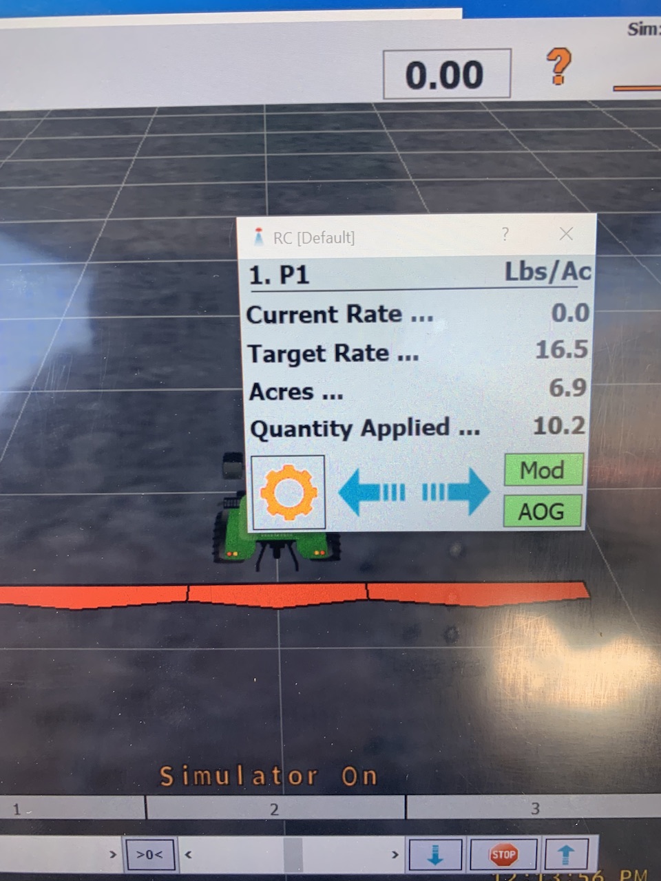
I just was messing with it some more. It will disconnect if I turn the master switch on even if all the boom sections are off.
Does the gear turn green when first connected?
It should only be orange if the options/simulate speed is selected or if the master on button is held in the up position for 3 seconds.
What is the primed start switch delay set to? It should be greater than 0 probably at lease 3.
I think I have it, I tried it just using on screen buttons, no switch box. It worked perfectly. I had a constant toggle in the switch box for master. I didn’t realize that was also supposed to be a momentary. It was having issues when I left the master on. If I cycle master up and return it to center it is working as it should. Thank you very much for getting back to me quickly
That would do it.
I am up and running. I have run the calibration. The flow meter is reading. It is calculating a rate of application when I drive and spray. If I press the ma and mb buttons on the cytron I can adjust the valve to above and below the correct application rate. The problem is when I drive it does not adjust the rate. It just stays at the same output rate, so the calculated application rate goes up when I slow down and down when I speed up. Is there anything that stands out to you in my settings, or something else I may have over looked?
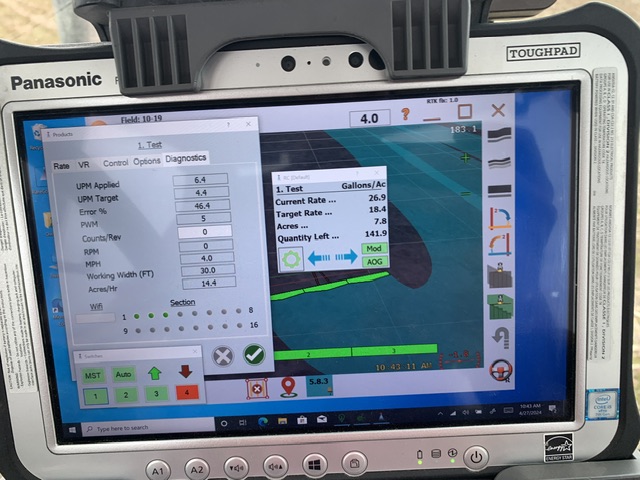
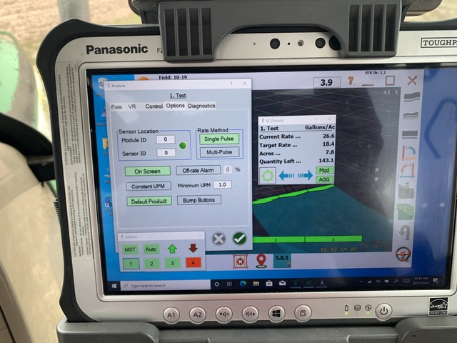
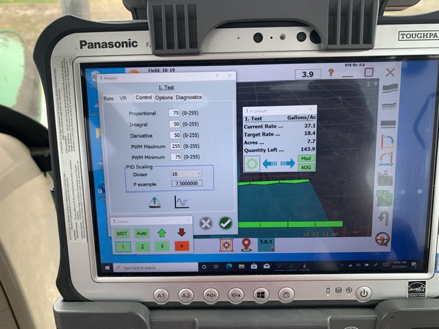
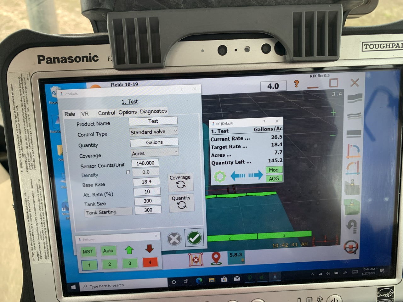
There is nothing really that stands out. I would set I and D at 0 until you have it working fairly well then adjust those to see if it helps.
I have just started testing the sprayer in the field and I have found some errors in the code. I have changed the teensy rate code but I haven’t had a chance to try it. I can change the nano rate code too, maybe it would help. I will leave the hex file here when I get it changed. PCBsetup can upload the file.
NanoRate.zip (56.1 KB)
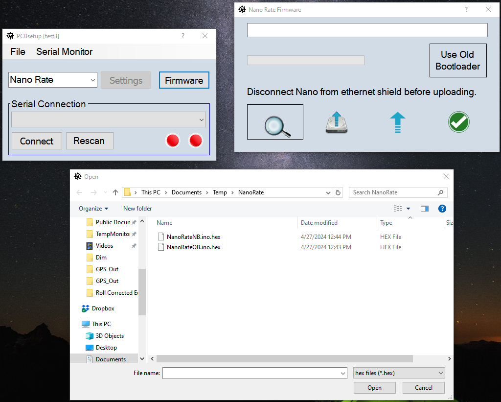
There are two files depending if you need the nano old bootloader version or not.
Pressing the MA and MB buttons really only confirms that power goes to the cytron and then to the motorized valve.
Use a simulated speed and put a multimeter on the wires from the cytron to the motorized valve, To see that you have something coming out.
How have you tested the polarity to the motorized valve to ensure it opens when you want more product and closes when you want less? Assuming it’s a direct control valve and not bypass control valve?
Thank you, we had some dry weather and are planting. Hopefully next week we can load that file and give it a shot
Thanks for the ideas. I was just pressing the buttons to make sure all the wiring to the motor was good and that the motor was still working after the sprayer was stored over the winter. I will have to do some checking. I am pretty sure the cytron is not sending anything to the motor. Even if it was wired backwards it should still adjust the rate, although in the wrong direction. When I drive the rate just stays rock steady. If it is over applying by 8 gpm it stays right there.