SMD PCB Project for an all-in-one compact PCB for AOG/QOG

Is these Parts are through hole parts ? and how can we install on this PCB board and other thing can we also soldiers connector our self ??? or all of them are smd based because JLCB not doing that for me think so

Screen Shot 2021-01-17 at 3.51.28 PM

all of them are SMD; there is another BOM for the THT parts (mind, that there are a lot of options and you don’t need all)
There are 3 reasons, that JLCPCB cannot mount these parts:

  • they don’t do connectors for any reason, but this is planned for the future they told me
  • they only mount parts LCSC has in stock. And the LPC54616 (you only need it for dual-CAN) is a part, you have to buy from digikey, etc.
  • like above, but sometimes, parts are out-of-stock. Press the “go back” button, and you’ll get another list, in which you can see the reason and may choose alternative parts

I ordered my first samples on Wednesday, and unfortunately the USB hub FE1.1 was unavailable. So I had to order it elsewhere and solder by hand…

Be sure to use the latest data from the Git, because I realized a small bug in the designator naming, so I’ll also have to mount someLEDs by hand… But that’s developing…

I know it’s only the 2nd, but it’s there any updates? Very interested in your design.

Thanks,
Kevin

PCBAs have arrived in Frankfurt; waiting for customs… I’ll keep you tuned!

6 Likes

No connectors is not a big deal at all.

But removing 90% of the soldering time is awesome. Being more compact is exciting.

Very interested how the first ones turn out!

3 Likes

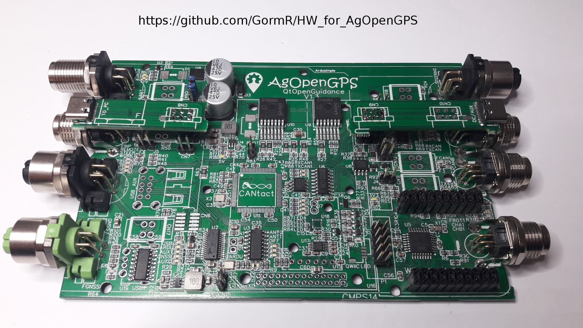
Full featured M12/M8 PCBA

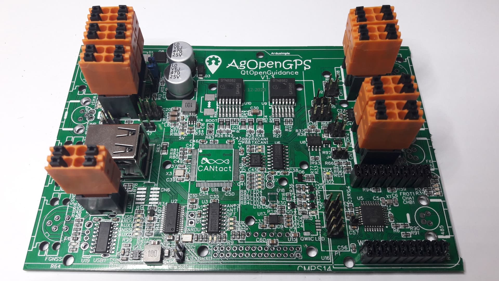
Full features PushIn PCBA

20210206_211315_resized
Autosteer PushIn PCBA

20210206_213150_resized
Soldering is no rocket science (but the 2 USB-C in the first picture took half an hour of my life :wink: )

Quick update with the first pictures. Already tested and working:

  • power supplies
  • USB hub
  • Nano bootloader programming

Known issues till now:

  • Some extra milling at the edge necessary if using M8 connectors
15 Likes

can’t wait to see the result, great job! :star_struck:

1 Like

20210207_010639_resized
Modbus is working, so Modbus relay modules can be controlled via RS485!

Python code of this example:

import minimalmodbus
import serial
#assign RS-485 interface to serial port (use “COM…” for Windows, “/dev/ttyUSB…” for Linux)
AOG_Modbus = minimalmodbus.Instrument(“/dev/ttyUSB1”, 1)
AOG_Modbus.serial.baudrate = 9600
Relay = 5
State = 0x0100 # possibilities: 0x0100 = on, 0x0200 = off, etc
status = AOG_Modbus.write_register(Relay, State, 0, 6, False)

6 Likes

Nice! those 485 output modules are all pre maid and cheap like borscht on Aliexpress. Can’t get much easier output setup than that! Also 485 can go a very long distance.

Very Nice boards you have created.

2 Likes

Great work!

1 Like

Made a small video about setting up the board (the first one I ever made!). There is also a German version.

I also added some pictures to my github folder (“documents”).

Will add more information in the next time there.

Tested yet:

  • USB hub
  • Atmel section with I/Os needed for AOG
  • power supply
  • motor driver
  • WAS input
  • RS485 / Modbus

Still untested:

  • CAN
  • ESP32 option
  • Bynav option
13 Likes

@GoRoNb Nice PCB, there is a relay for 6/2 valve if you run hydraulic control?

there is enough cooling on ibt2 if you use electric motor?

1 Like

There is a general propose 12V output you may use for anything:
grafik
The coil of the relay can be connected between the output and +Battery.
I never worked with hydraulics; do you have a link for me? I’ll double-check…

The motor driver has an on-resistance of about 7mOhm. Assuming 5A of average current, we have 175mW + some switching losses for each of the two drivers. Should be no prob even in summertime.

1 Like

Look at steer.png in AOG support files, (dir1 / D4) the blue arrow care you put a small relay on to pull 6/2 valve, when it is pulled the steering wheel can not be used, will not be optimal with your suggestion

1 Like

Not 100% sure, but if you only need the digital signal DIR1/D9, you can connect to the highlighted pin in the middle of the picture next to the text “R59”:
grafik

1 Like

grafik

Uuups, testing dual-CAN will take a while :flushed:

1 Like

I’ve to correct my answer; the Cytron in the steer.png confused me…

I’m using a circuit like the IBT-2, so the DIR1_RL_ENABLE = D4 is the signal to control the 6/2 valve. It can be found here (underneath the yellow “D1” text):
grafik

I also found an “old” link discussing the same topic: Hydraulic valve info from Telegram group - #90 by Richardklasens_admin

There is another option I would prefer: Just add two lines of code, copying the D4 bit to the D5 bit and use the signal available at the “Steering” connector:
grafik

@GoRoNb I wrote wrong, you are right it is D4 we use to activate a small relay for 6/2 valve when we are in IBT2 mode, can not fit this relay on your PCB?

1 Like

Agree, nice idea to add it although hydraulic steering is critical in Europe… But no relay; that’s old style. Protected MOSFETs like BTS5030-1EJA are the smarter and more reliable choice.

4 Likes

@GoRoNb I do not have a grand sense of electronics components, hope you find room for it, believe there is a part that uses hydraulics.