PCBAs have arrived in Frankfurt; waiting for customs… I’ll keep you tuned!
6 Likes
No connectors is not a big deal at all.
But removing 90% of the soldering time is awesome. Being more compact is exciting.
Very interested how the first ones turn out!
3 Likes
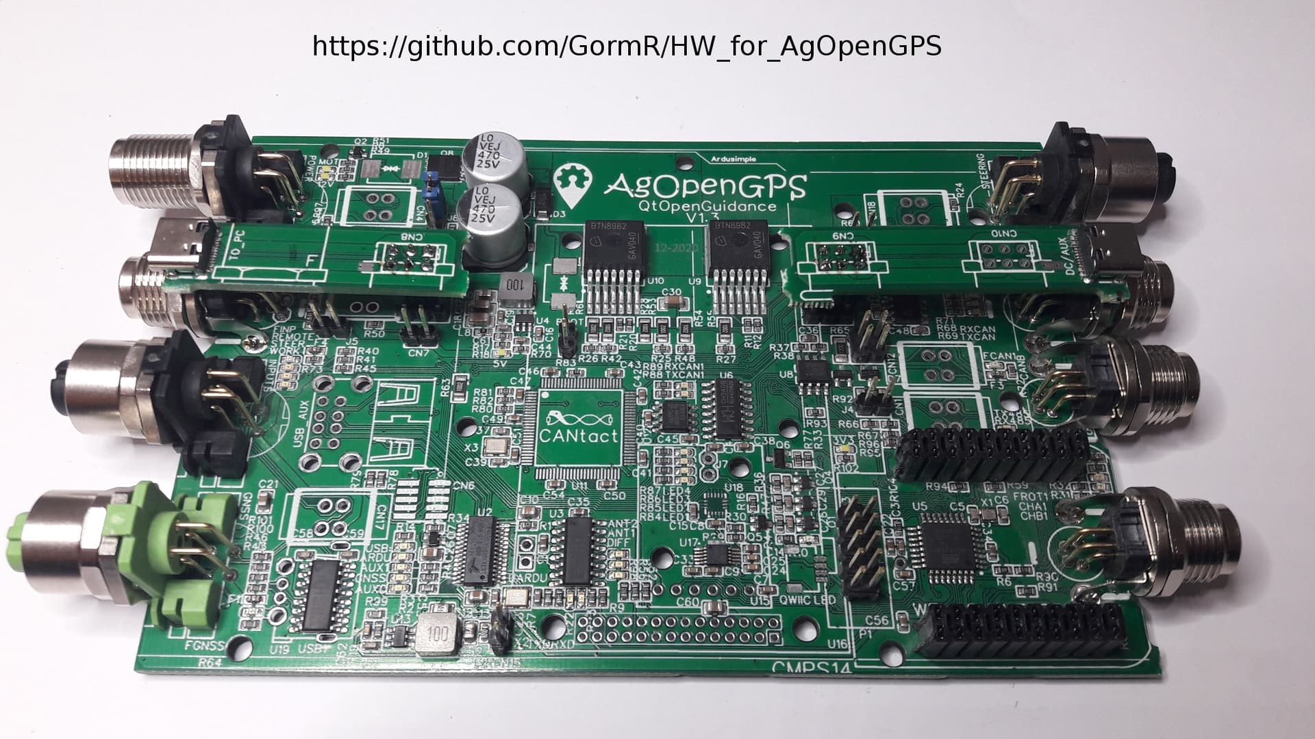
Full featured M12/M8 PCBA
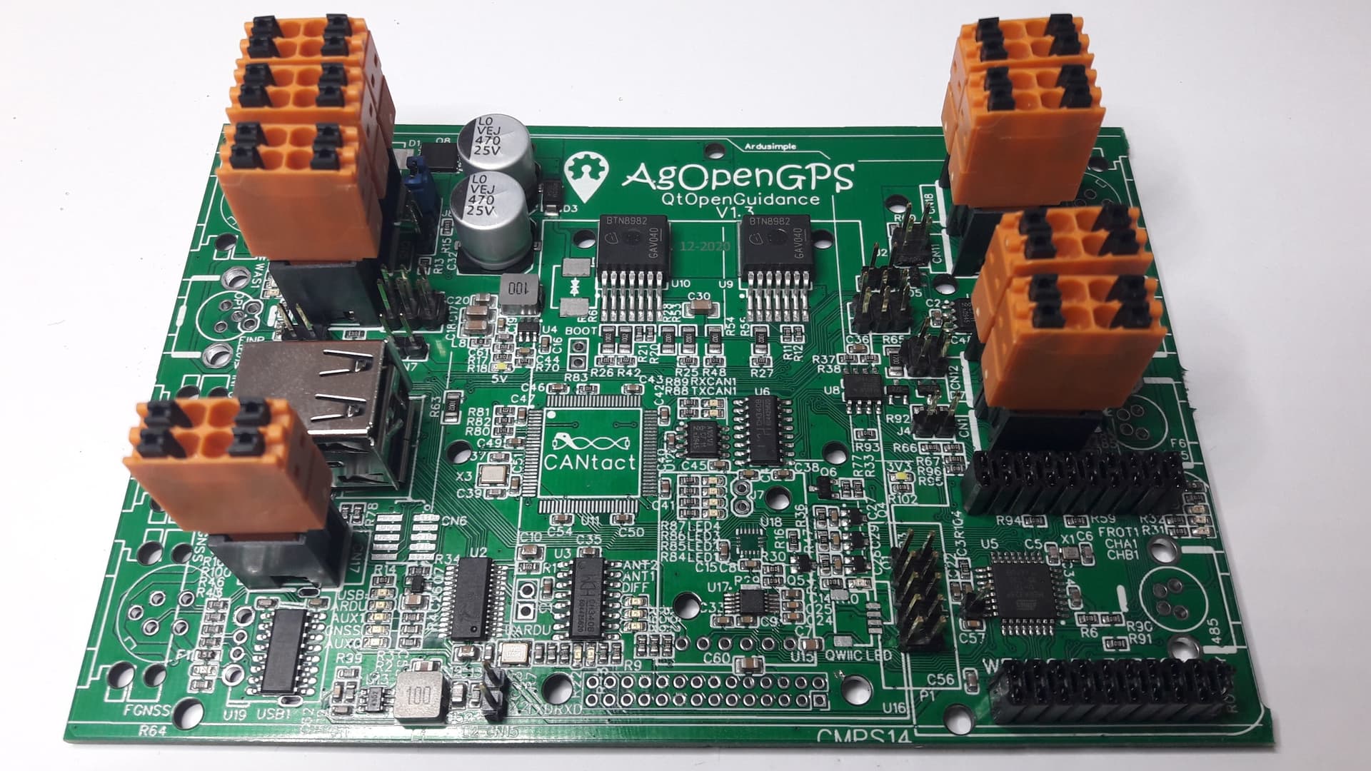
Full features PushIn PCBA

Autosteer PushIn PCBA
Soldering is no rocket science (but the 2 USB-C in the first picture took half an hour of my life ![]() )
)
Quick update with the first pictures. Already tested and working:
- power supplies
- USB hub
- Nano bootloader programming
Known issues till now:
- Some extra milling at the edge necessary if using M8 connectors
15 Likes
can’t wait to see the result, great job! ![]()
1 Like
Modbus is working, so Modbus relay modules can be controlled via RS485!
Python code of this example:
import minimalmodbus
import serial
#assign RS-485 interface to serial port (use “COM…” for Windows, “/dev/ttyUSB…” for Linux)
AOG_Modbus = minimalmodbus.Instrument(“/dev/ttyUSB1”, 1)
AOG_Modbus.serial.baudrate = 9600
Relay = 5
State = 0x0100 # possibilities: 0x0100 = on, 0x0200 = off, etc
status = AOG_Modbus.write_register(Relay, State, 0, 6, False)
6 Likes
Nice! those 485 output modules are all pre maid and cheap like borscht on Aliexpress. Can’t get much easier output setup than that! Also 485 can go a very long distance.
Very Nice boards you have created.
2 Likes
Great work!
1 Like
Made a small video about setting up the board (the first one I ever made!). There is also a German version.
I also added some pictures to my github folder (“documents”).
Will add more information in the next time there.
Tested yet:
- USB hub
- Atmel section with I/Os needed for AOG
- power supply
- motor driver
- WAS input
- RS485 / Modbus
Still untested:
- CAN
- ESP32 option
- Bynav option
13 Likes
@GoRoNb Nice PCB, there is a relay for 6/2 valve if you run hydraulic control?
there is enough cooling on ibt2 if you use electric motor?
1 Like
There is a general propose 12V output you may use for anything:
The coil of the relay can be connected between the output and +Battery.
I never worked with hydraulics; do you have a link for me? I’ll double-check…
The motor driver has an on-resistance of about 7mOhm. Assuming 5A of average current, we have 175mW + some switching losses for each of the two drivers. Should be no prob even in summertime.
1 Like
Look at steer.png in AOG support files, (dir1 / D4) the blue arrow care you put a small relay on to pull 6/2 valve, when it is pulled the steering wheel can not be used, will not be optimal with your suggestion
1 Like
Not 100% sure, but if you only need the digital signal DIR1/D9, you can connect to the highlighted pin in the middle of the picture next to the text “R59”:
1 Like
Uuups, testing dual-CAN will take a while ![]()
1 Like
I’ve to correct my answer; the Cytron in the steer.png confused me…
I’m using a circuit like the IBT-2, so the DIR1_RL_ENABLE = D4 is the signal to control the 6/2 valve. It can be found here (underneath the yellow “D1” text):
I also found an “old” link discussing the same topic: Hydraulic valve info from Telegram group - #90 by Richardklasens_admin
There is another option I would prefer: Just add two lines of code, copying the D4 bit to the D5 bit and use the signal available at the “Steering” connector:
@GoRoNb I wrote wrong, you are right it is D4 we use to activate a small relay for 6/2 valve when we are in IBT2 mode, can not fit this relay on your PCB?
1 Like
Agree, nice idea to add it although hydraulic steering is critical in Europe… But no relay; that’s old style. Protected MOSFETs like BTS5030-1EJA are the smarter and more reliable choice.
4 Likes
@GoRoNb I do not have a grand sense of electronics components, hope you find room for it, believe there is a part that uses hydraulics.
Yes, there was some space left to add this function via U14:
For assembling this part, edit the BOM file (“xU14” => “U14”, delete “R59”)
The 6/2 output will be on this track:
Furthermore you can put a solder joint on the bottom and remove “R76” + “F7” to make “SERVO+” to “-MOTOR” (= “-Battery” via emergency stop button), so that all signals to the valves are on “CN18”. That avoids current loops and you have a failsafe switching via the positively opening stop botton.
2 Likes
Looks great! Nice video, can’t believe it’s the first one. I love the small design and enclosure. Still can’t believe its cheaper than ordering all the parts and soldering yourself. I am going to try to place an order. Great job!
4 Likes
I think for most farmers just trying to get it to steer this is 100% hands down the way to go.
The only thing I can see changing just for the fun of tinkering is having a socket where the nano chip is to accept a teensy4.0, or I guess I could learn ESP.
Hopefully V4+ is still compatible it sounds like quite the revision in the works.
But very good job this is very excellent work, I wish I had the skills to build hardware like this.
1 Like