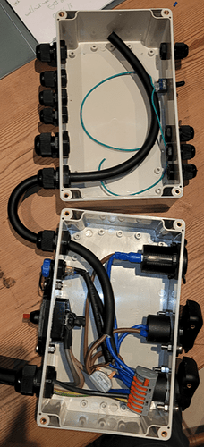
that’s difficult to say via internet. The picture shows very good cables of course. With 12V you have much more headroom of course, but maybe a bigger electrolytic cap may also help
I assume you mean C2 (220 uF). What capacitor would you suggest?
External power did not help. Could this be a symptom of a badly soldered FE1.1s chip?
good question. if the data was lost, it pretty much the same than power loss. There is a trick: if you put ice spray (for electronic) on the FE1.1: is it stable? Normally this shows bad solderings quite good
Back at the table I have narrowed it down and it appears the activation of an actuator just next to to the Phidgets motor induces a very short communication break. The closer the two are, the worse. It even happens when the actuator is powered from a different source with no physical connection of the circuits. Some electromagnetic effects must be at work.
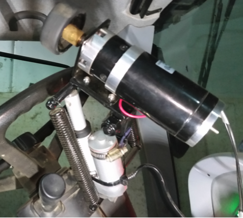
All 3 autosteer kits I built have this same behavior so I’m thinking the central units are built and soldered just fine. Either the central unit has some undiscovered weakness or else this particular setup with actuator-motor is the coincidental problem causer. Which I find strange because I was using it for 3 years in a setup with everything connected with bluetooth modules (HC-05).
Someone who recognizes this behavior or might know what to do/try? My next field test will be without actuators for sure. Which is a bummer, it was a quick and easy way to disengage the steering motor.
the 0V signals of power stage and µC part are intentionally decoupled. Likeley you have connected the supply to the power stage directly to any 12V high power socket. How did you connect the supply of the µC part / tablet? Via the 12V charger of the tablet?
The 12V+ and GND are all the same I think. In the pictures you see an open box where big power enters straight from the battery with a fuse and interruptor and some peripheral power sockets among which a PD usb-c car charger for the tablet. A power line enters the second box on top where some permanent connections are made, e.g. a switchable 12V/24V motor supply and where the industrial connectors for the central unit leave the box (among which the power connector with 12V from the power line and for the motor driver 12V or 24V from a converter). Also leaving here are the A and B wires for the motor (and the actuator) of ± 2 meters.
I have a switch on pins 3-4 of J8 that shuts the central unit on/off independently of the tablet (see a previous post), regardless if it is connected with a usb-c cable to the tablet or not.
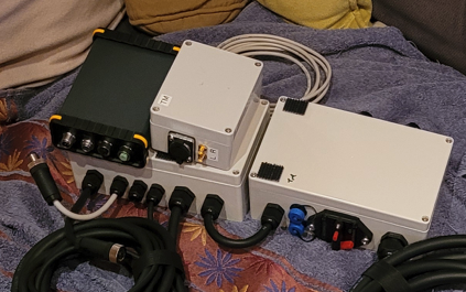
looks good to me. The USB and the charger cable are close to each other and not next to the motor or main supply cable?
No not at all. The tablet is a surface go which has a dedicated power port and a USB-C port which can charge too. I tried two options: adapter cable usb-c to power port + usb-c cable to central unit and secondly, usb-c hub with a charging usb-c port to charger and a data usb-c port to central unit.
what kind of actuator is it? do you have a link for me?
It is the Stroke 30mm, 12V 200N 45mm s version here:
I switch + and GND on the wires with this module:
yes, nice actuator. I’ve the same type running on my Raspberry board w/o any issues. But in that case, it’s used as steering motor, so driven by the internal power stage.
Two things come into my mind:
-
Please do NOT connect the GND of the switchboard (the red “G”), just the trigger input “T” via an 1k…10k resistor in series (I’m scary with µC pins…)
-
Put a resistor into the actuator lines to limit the inrush current (e. g. 1R: 2 Stuks 20W 5% Cement Weerstand Vermogen Weerstand 0.1 ~ 10K 0.1R 0.5R 10R 50R 0.22 0.33 0.5 1 2 5 8 10 20 22 30 50 100 1K 1.5K 2K Ohm|Weerstanden| - AliExpress)
An elegant way to control that signal is the signal “OUT”: with a jumper on J8 (1-2) and Q6 mounted (can be a standard MOSFET when you have a resistor in series), the µC is still fully protected.
Do you mean it can’t hurt to put a jumper on pins 1-2 of J8 anyway? Q6 was already SMD mounted. This does not help so far.
The arduino is just as susceptible to deconnections as the GNSS/roof unit I found out.
I’m starting to suspect the usb-hub again, because I now found something peculiar in 2 of 3 kits: that the hub connects only with the usb-c connector one way and not or only partly upside down… ![]() sigh!
sigh!
Are these corrections described here, critical for functioning? As I may want to check if I soldered them well enough last year… SMD PCB Project for an all-in-one compact PCB for AOG/QOG - #163 by GoRoNb
You have two wires between the central unit and the actuator switchbox PCB, right? Please disconnect one of them (GND = 0V, “G”) and put a resistor to the other (“T”) in serial.
Hm I don’t get it. I have it wired up like this, it was in the box, but here for testing on a separate battery with no physical connections to the central unit. White and yellow are connected to a button. Can only short that button to do something?
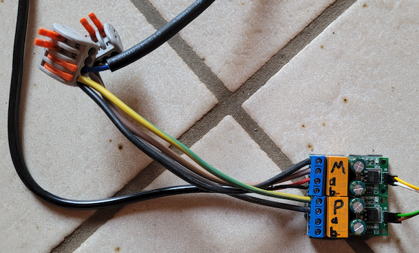
No physical connection so the disruption must somehow enter the central unit at the A and B wires of the Phidgets motor or the wires of the steer button (steer input and 12V) which are both located just next to the actuator.
Ahh, I was thinking, you do it automatically with the activation signal of the power stage like those using a 2-6-valve (or whatever ![]() )… Can you say, if the interruption is when the motor starts moving or when it stopps (end position reached)? I’m asking because in one case, you have a high current and in the other EMC radiation from the switching spark.
)… Can you say, if the interruption is when the motor starts moving or when it stopps (end position reached)? I’m asking because in one case, you have a high current and in the other EMC radiation from the switching spark.
Beginning or more halfway, hard to say. It’s roughly a 1 second movement of the actuator in/out or out/in.
that’s really crazy, because the steering motor needs much more current than that linear drive. I would try a resistor in series (maybe you have a long wire at hand to test).
After having solved that, you may also take the signal “steerenable” (available at J7) and route that to the “IN” pin of such a board. This will engage the motor, when AOG is in control and disengage when AOG is idle automatically.
I tried and put a 50m 0,34mm2 wire in series with just as much deconnections. However it slowed down the actuator so that I could see deconnection (LEDs on the central unit board) happens at the end of the actuator travel when it stops.
hmm, so likely something like discussed here.
I would start with a small cap in the motor lines, e. g. 47n. If this doesn’t help, you should solder them directly to the motor:
The cap values don’t matter so much, so something between 10n and 100n. If you have a suppressor diode with something between 18V and 47V, you can put it across the motor contacts, too.
If you have a snap ferrite from another cable, you can try this first. Put it next to the motor. Old VGA cables often had a ferrite bead, too.
Thank you for your help and suggestions. I threw the actuator out this morning… I did half a day of field work with no disconnections at all. Phew! So the good news is the central unit looks to be performing well and my troubles were due to that actuator and that only.
I’m looking into a mechanic alternative with a push-pull toggle clamp lever thingy like this…
