I note one thing that the high temperatures on last days cause warping on the universal clutch i had print with black PLA.
Now i try to print them with PTEG.
Thank you.
My plans changed as I will not be able to put that bracket around where steering wheel turns because of increased resistance and load on motor.
I am currently looking for options to mount my motor. I have more than one tractor to mount just like this. Any ideas?
Hi
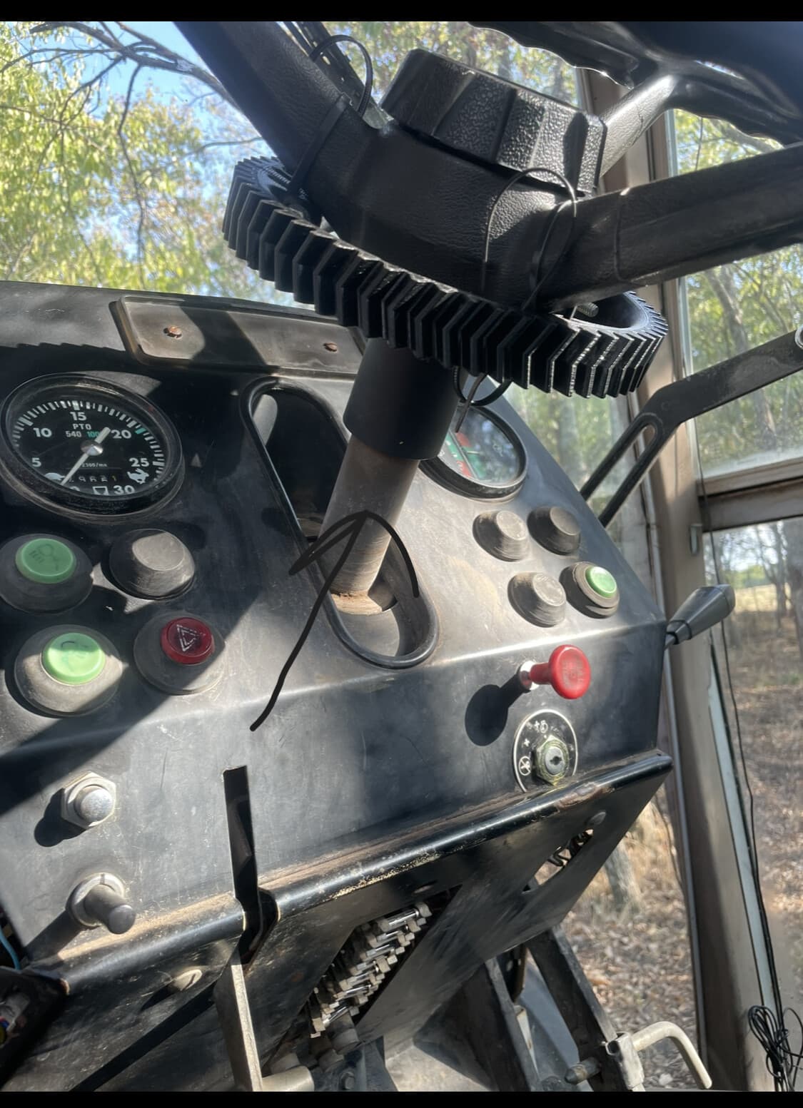
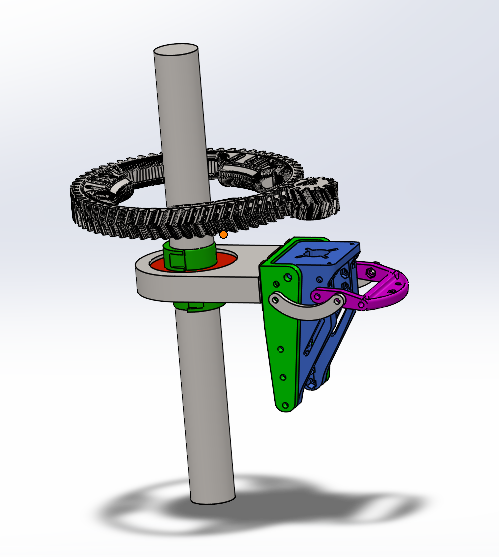
i see on the second picture a mistake of alignment between the two gears they must be perfectly align
the fixation of your motor is too far that make flexibility.
I have a question
Does this colonn rotate or no?
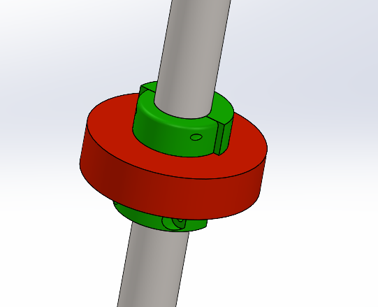
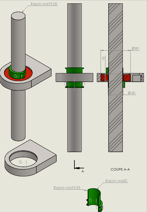
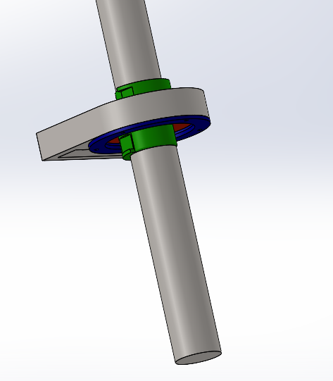
If only the steering wheel rotate you can fix the motor with the piece i send you the STL maybe you will have to modifie diameter to fix them fermely.
I hope i was clear.
Yes the column you pointed to rotates with whole steering wheel. That diameter is 1.5 inches. I modified your file and tried to think of ways to use it so it would slide freely. I think a bearing would be tough to do, sill learning fusion.
Is there any examples of a bearing being used someone can link here? I looked and can not find a steering wheel setup like this one I have.
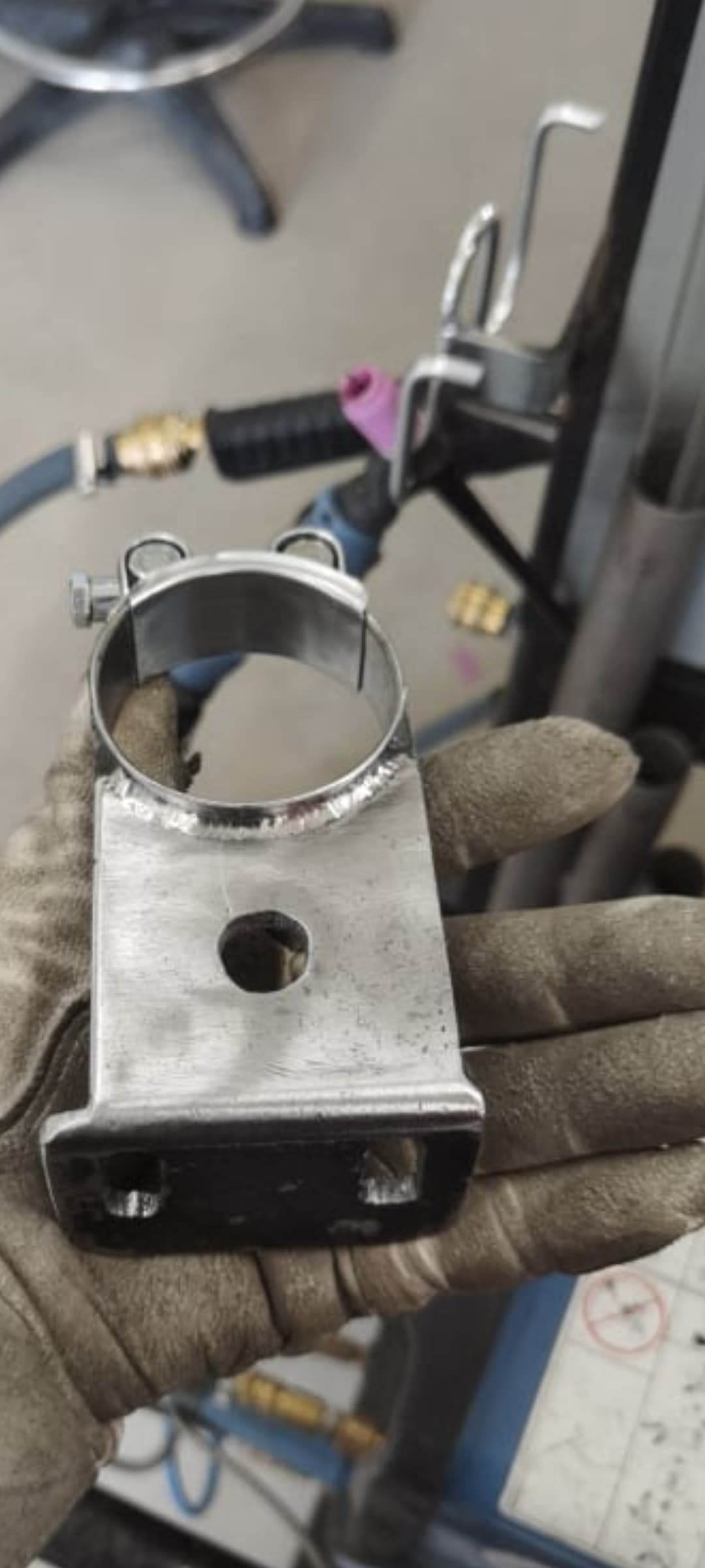
Have a look in the steering mount file picture thread in the new holland section and you’ll see what i done. Basically used a wide pipe clamp and fixed that to a non moving part then got some flat plat shaped to fit the clamp, this might then get you away from the steering wheel a bit and give you a few more possibilities
This is the picture i found that inspired me
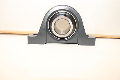
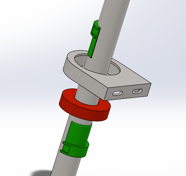
Thanks. Got me thinking. Since mine tilts and telescopes, and the center moves with steering wheel, would a bearing pillow block be sturdy enough to work? I would have to spacer it with washers away from steering wheel if I did.
I like the idea, did you draw that in fusion? I would need the split spacer to go around 1.5” shaft. What I’m thinking is I would need 2 bearing sets maybe to support the weight of the motor and to stabilize due to bearing width being narrow. I have a 62082rs which is 40mm id, 80mm od, 18mm width.
I appreciate the drawings and I hope I can find time to work with them on future application installations. Since I don’t have a 3d printer yet it is tough to try some of these great ideas. As I have been sending off stl files to print.
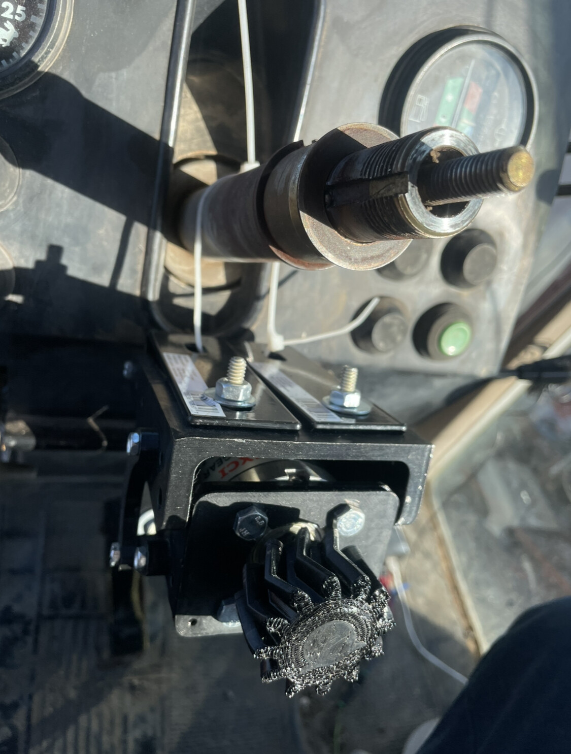
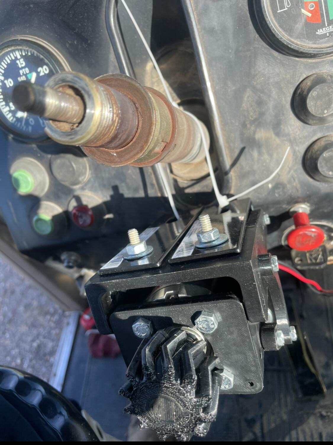
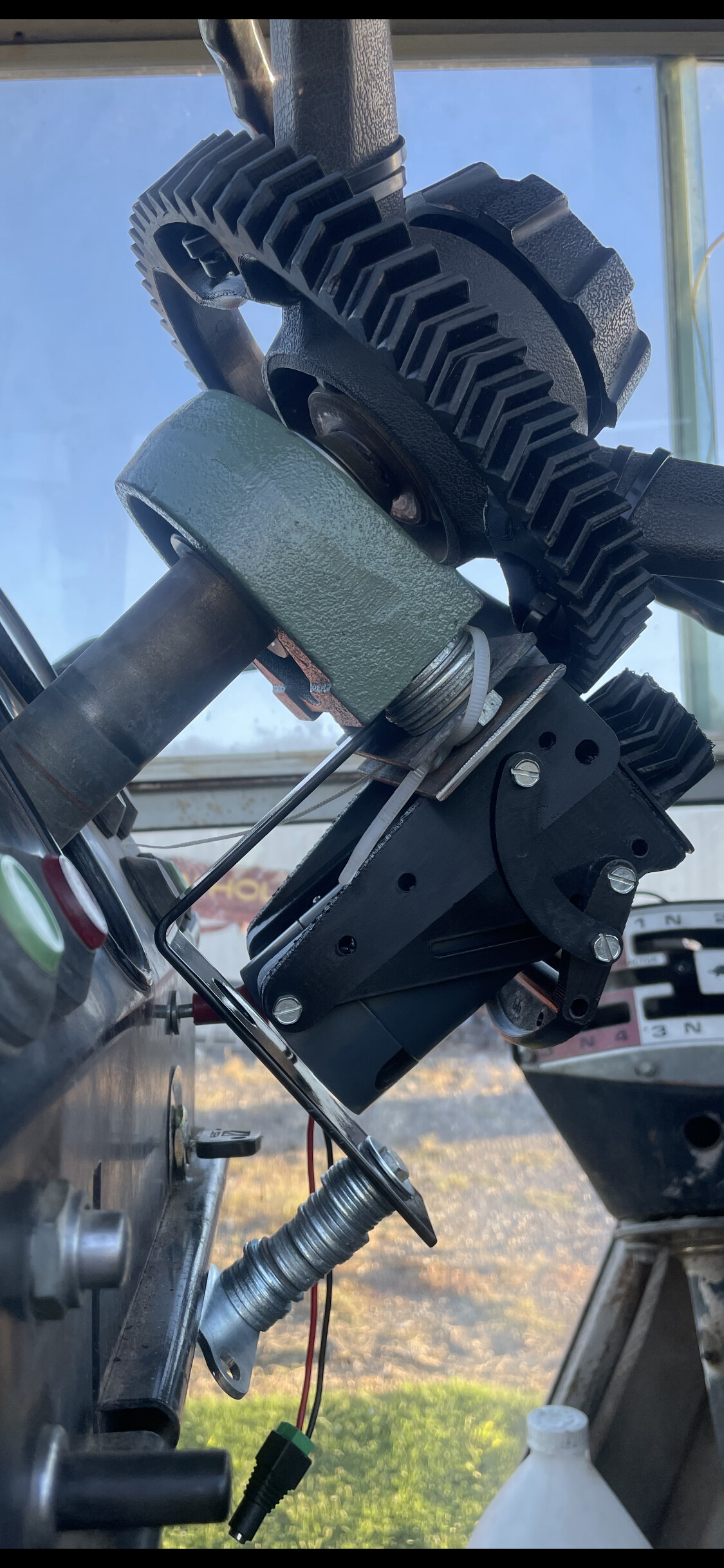
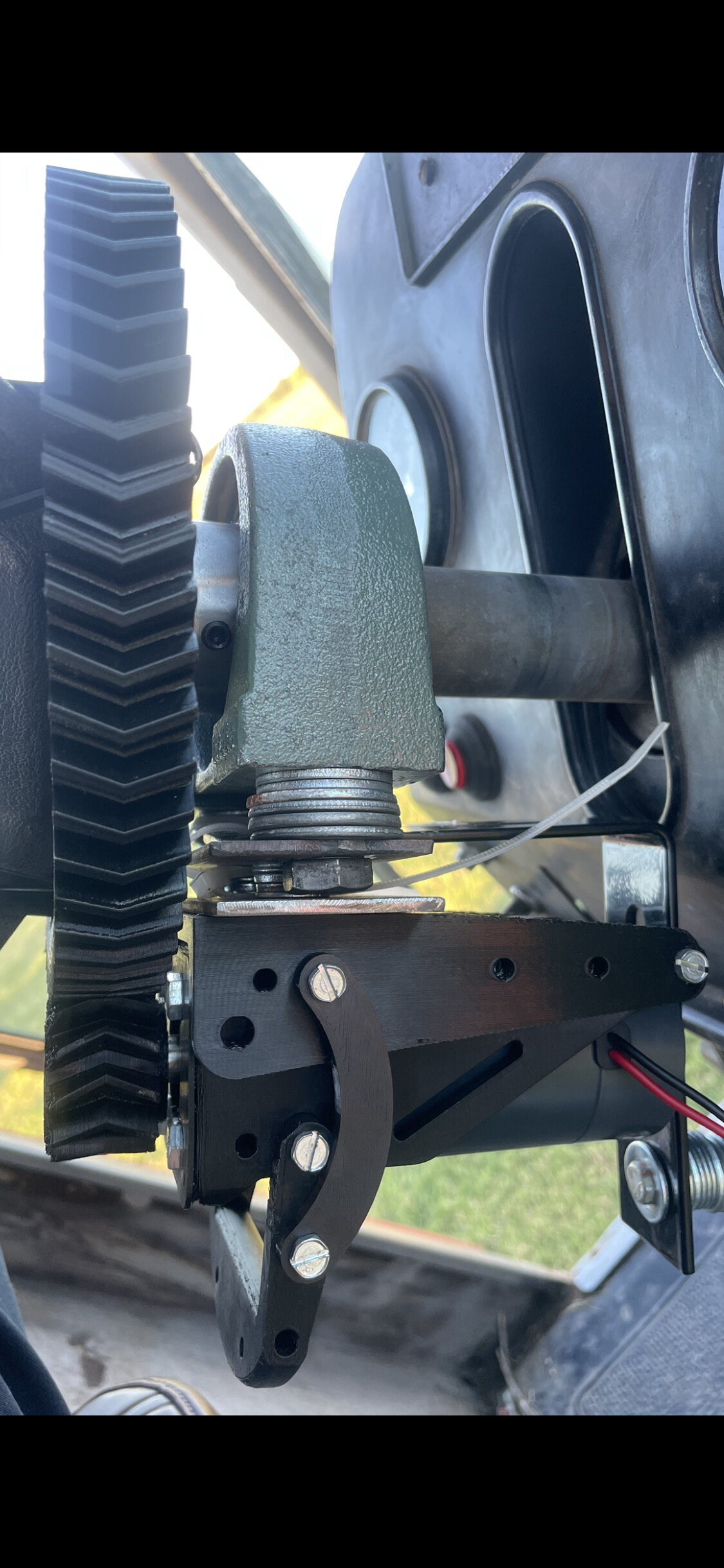
I wanted to update the group of what I finally did that works for these Massey models. They have a 1-1/2 steering shaft, so I went with a tapped base pillow block bearing.
Works really well, I got 2 pieces of flat metal and drilled 2 holes for bolts and used washers to get to the distance needed to align with the steering wheel gear. Then drilled 2 more narrow holes on the outer flat metal to attach the 3d printed motor holder.
Used the support bracket I had previously used for the anti rotation finger.
I’m Spanish and I’m very interested in such a motor. In Spain there’s a group of farmers sharing experiences but all of them use Philgets or chinese reduction motors. My question is.
How do you join the shaft to the small gear (driver gear) I mean, I don’t see how to do it.
Haven’t got a picture handy but the phidgets motor on the shaft on the motor has a keyway slot in it and the small drive sprocket has an extra spline in it and they just slide together. Very simple easy to assemble/disassemble and it works a treat