Nano can not be connected to arduino ino at same time, so shut down arduino ino, to be sure.
1 Like
I’m closer, i get at red compass with a turning arrow as i turn the wheel angle sensor. But i cant get the icon to turn green, where it should be when autosteer is enabled.
When i look in AgDiag, the steer switch is red, can’t get it green.
Are you absolutely certain the board has power? You have 12v connected to the Cytron and USB connected to the nano?
This problem is most often a simple power issue.
Depending on how you have set things, in program.
This is how I start autosteer, I use a momentary switch.
First open field and make AB line.
To activate autosteer I press buttom right corner icon, then I can start autosteer (and turn off) with the momentary switch.
I am having the same problem.
Hi, 4n33 didn’t work no matter what I did. I set up the 4n33 test circuit and it was solid in the test. All pcb is perfect. The pcb I used in the test is working normally. I’m changing arduno, it doesn’t work. Arduino nano v3 picks 4n33?
No, it doesnt have to be an original nano, i have two autosteer boards both use clones
How did you end up solving the issue?
Are you still having issues?
I bought arduno from 3 different brands. running circuit. I bought the same arduno. Unfortunately it didn’t. I reassembled the pcb, it still didn’t work. 4n33 doesn’t work. I have 6 4n33s of 2 different brands. I’ve done a robustness test 4n33 they’re all good.
Whats exact problem your motor wont turn because 4n33 is not shorting D6 ? just bypass optocoupler solder it to make short and use switch normaly to turn on steer switch.
Idk why are there optocoplers on pcb is it for 12v powered switches?
1 Like
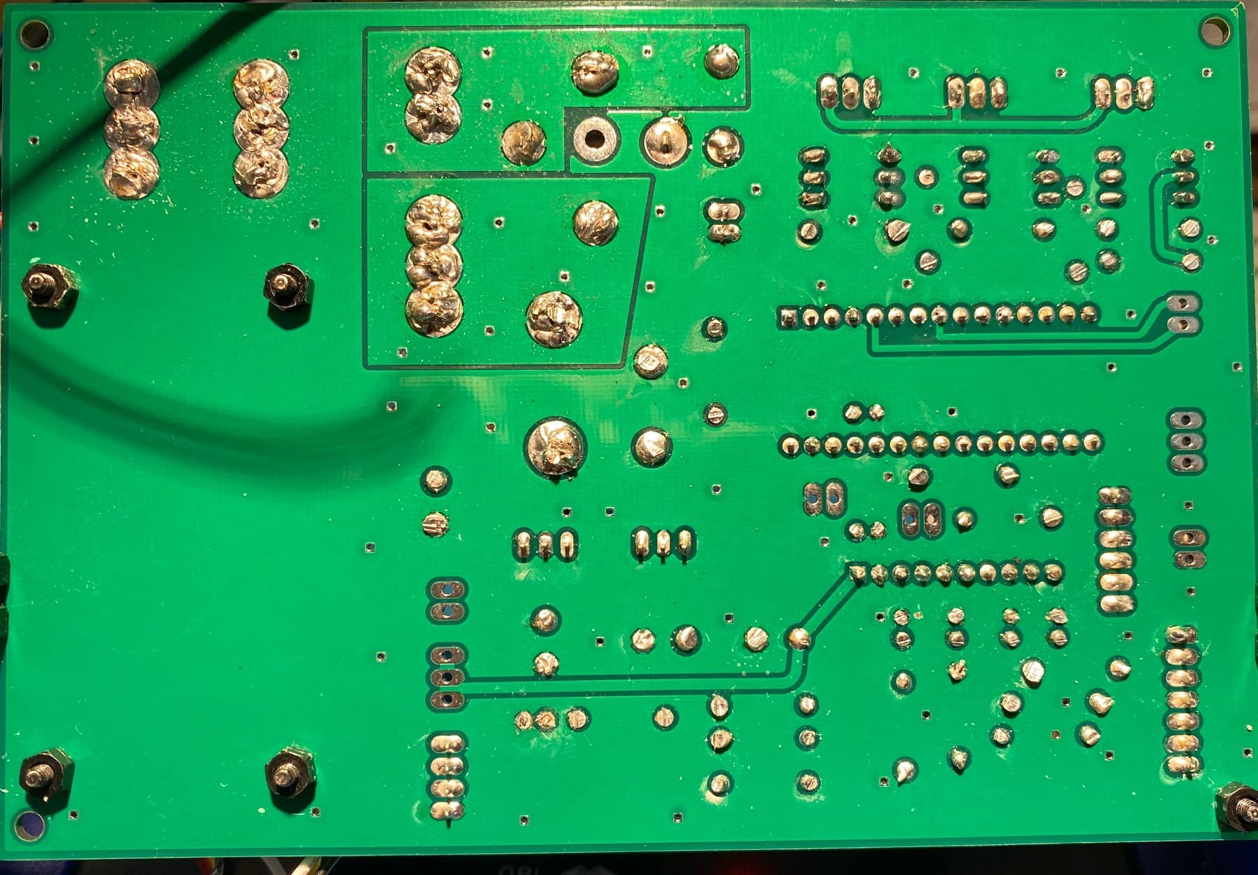
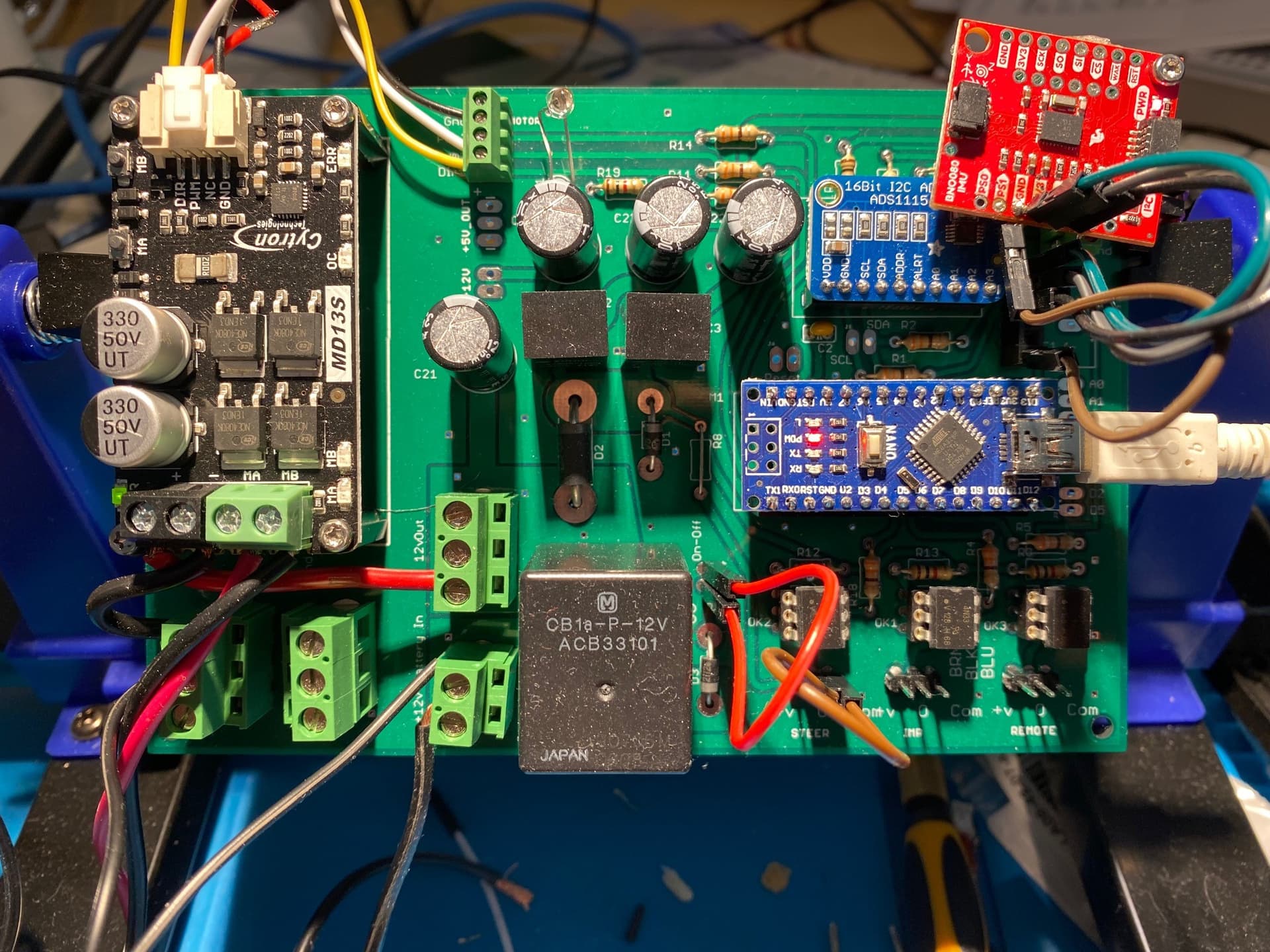
Post a picture of your board, both sides and your motor controller
I don’t have 100k resistors on hand. I’ll get it and test it during the day. I will keep you informed of developments.
Check opticoupler orientation. I put mine in backwards, motor wouldn’t turn. Also confirm steer switch wired correctly
You can probably use anything from 10k to 500k.
I tried, no solution. where could i be doing wrong.
Have you already increased Proportional gain in drive settings? If not, try to set firstly to 200.
Do you have 12 v at the resistors just before the optocouplers?
test adaptörüm 9 volt. Dirençler de 9 volttur. pcb’yi tekrar kontrol ettim. Ben de herhangi bir sızıntı görmedim. dirençler, diyot, hepsini tek tek kontrol ettim. sorun yoktu.
I have tested all yours tips…
Proportional gain to 200
12v at the resistors befor octo
Octocoupler orientation, with the little notch pointing upwords.
Here are some pictures of my pcb…
If i press the test buttons at the motorcontroller the motor spins…
Next to check is voltage at the arduino pin.
Is it 5v when switch is off, and the chance to zero v when switch is on?
I mean steer switch.
And off course power must be on .