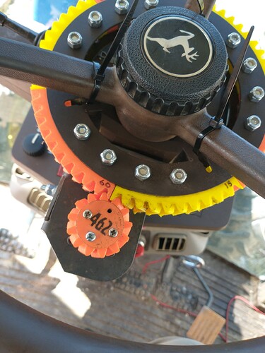
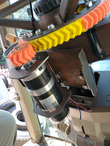
I’m having trouble slicing large gear. Not sure what I’m missing. When i lay gear flat it comes up grey and won’t slice. Any idea what I’m doing wrong?
Hello. If the object turned gray, it means that it exceeds the maximum of the board. You have to place it differently by moving or rotating it to fit.
By default you have skirt support that will add 3 lines away from model that will push it out of workspace, try turning off support and make sure that you have correctly selected printer maybe its too big for your workspace.
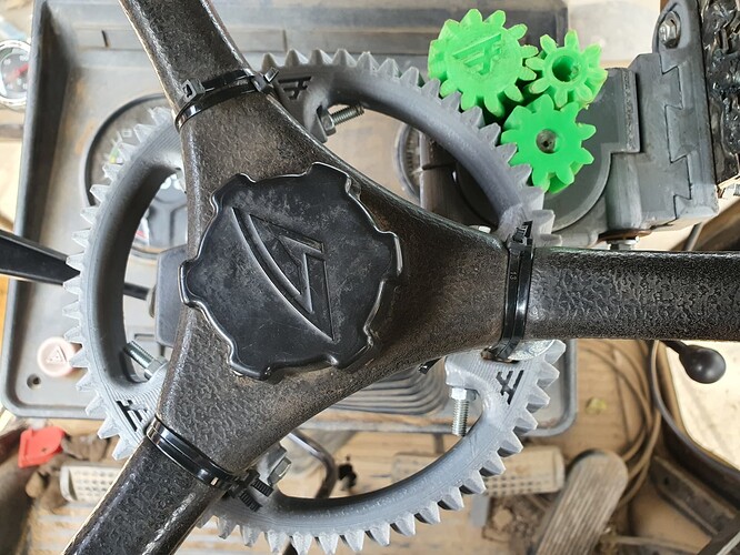
You have segmented big gear stl files its in 3 parts and you connect them with m6 bolts.
Switched 12 teeth gear for 9 to have more power (even so 80 min pwm).
Not exactly sure what is going on with your triple gear dual motor system?, but I like it! Looks very cool
Found my problem. Still was using raft instead of brim from a previous print.
Its one gear those 2 are failed attempts I placed them there for image, 12 was too much and 8 was too weak 9 is lowest that works on phigets with this 3.25 module.
Radmuffins, Hi. Can you share the 9 tooth gear file?
Thank you. I have this mount too. Thanks PotatoFarmer.
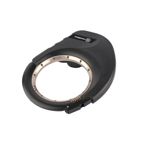
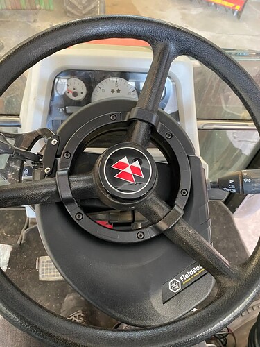
I saw a guy dismantling one of those on tik tok, it has an electromagnetic clutch, it looked like the motor sat transverse and ran a worm gear.
I wonder what that clutch is worth?
With all the shakeup with PANDA and UDP, I have been pondering moving the cytron right onto the motor, then the motor cables would be the absolute shortest. It would take an extra nano, and ethernet port but then it would be modular.
Since everything is close in cab, instead of physical ethernet it could steer by bluetooth. If it steers by Wifi, you would have to have the phone giving the tablet internet by usb connection i think.
Then steering would only have power connections with wireless, how much do we all trust short range wireless?
Someting like all in one module around motor or just cytron? What about heat and magnets from motor ?
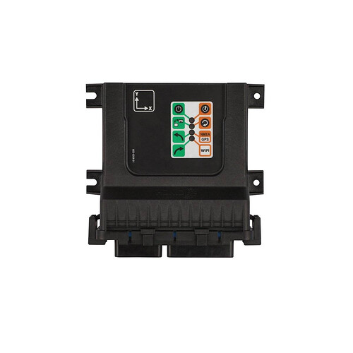
Is that fieldbee board inside with motor?
really nice motor holder @PotatoFarmer maybe with smaller pcbs it can be made all around motor and fan to cool evrything down. That would be great step in portability, bouth motor and pcb taken with you from one quick attach system. BNO dont use magnetometer so it will work there main things left on tractor are antenna and WAS sensor.
thoughts?
The IMU + GPS I think are better together. Gps module
I am just thinking of having cytron, acs712, 24v booster and a nano with udp for coms combined for electric steer. Electric steer module.
This would let you mount the gps and imu outside on frame or in cab
Electric steer would be just power if done by bluetooth
One outdoor poe switch would plug in Cameras and section control.
Make the lego pieces simple and fit for duty.
So now we have 4 modules PCB,IMU,GPS and section control. and additional things like camera.
From my understanding with teensy 4.1 it is planed to have IMU+GPS+teensy (GPS module), nano PCB steer module, and section control nano module?
GPS module on roof just one PoE ethernet cable to roof easy removal of antenna and box.
Steer module around the motor (easy 3d printable enclosure). 12v power and wifi/bluetooth, or normal ethernet to tablet.
Section control PoE for nano and 12v for power.
With PoE splitters a lot of expensive PoE equipment can be circumvented and feeding 12v or 48v directly to cable if for 5v volatage drop is too high (which would require stepdown at other end).
How much power is GPS module using?
The gps can draw 2A. Mostly poe would be handy for cameras. AOG already has a webcam viewer built in.
But thinking of interoperability, some tractors may use electric steer others may use hydraulic or CAN. So for some you may only use the panda module ever.
If the phidgets was its own module, then if you want electric steer you build that module.
So far this is just an idea I am discussing nothing written in stone. But it might also reduce motor heating having cytron to motor wires 15cm or less vs a meter across the cab. Also its easily back compatible. With UDP everyone is on a party line for information, so it does not matter too much where it goes in or comes out.
I think to keep it easiest with Agio and udp you would need a second usb wifi adapter, or router, if simultaneously wanting to use your phone for corrections and wifi to steer. Though there may be another work around.
https://www.aliexpress.com/item/1005002034242680.html
From PoE directly to usb 5v 2.4A, GPS module will work from PoE.
Cameras are easy just feeding 12v to wire.
I have rtk2b and PCBv2 powered from USB if I forget to switch it on and it works from 500ma USB port.
Thats why all in one PCBs are limiting I really like modular system of AOG from hardware to software from simple light bar to top of the line autosteer and everything in between.
I think this whole project was heading towards a polished finality around the original board. But too many exciting new upgrades to add to the Spaceship.
After the announcement of v5.5 being a long term stable release, It got everyone’s imagination going again.
Frees up room to break things.

Its a lot of different ideas and directions all at once. But its cool how much change we can make without too many new components.
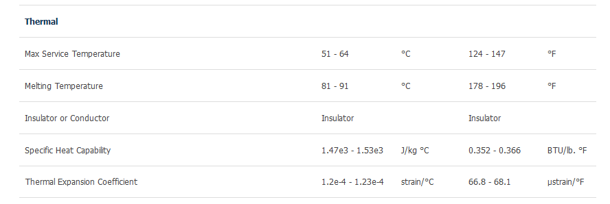
I’m coming around to the idea of using the gear driven solution from PotatoFarmer. Temperatures can hit 130F in the cab of a tractor parked in the hot summer sun here. For that reason and the impacts in some of our fields plastic makes me a little nervous. That said, I’m planning to print a similar gear arrangement but will use steel/aluminum to hold things together where I can. The wheel gear will be made of 6x 60degree segments, keyed together and sandwiched between steel plates top and bottom. I’ll add a picture of that once I’m through the printing.
It will be neat to see, your top cab temperature is about the same as the top operational temp for PETG.
I understand you point of view but the 3d printing in hot temperature can be hot and “plastic” condition but not liquid to loose it except if you work in dead valley or similar
After start the tractor the cab will be cool by A/C the 3D printing will be cooling .
If you want to do metalic parts you can be inspired by my concept that is more friction type with mix of steel and TPU
Those temps are probably in the rear-view mirror for this season. I’m using the PET-G (instead of TPU) because it’s a little easier for me to print at this time.
Here are a couple of pics…
I printed 6 segments of different infill % just to see how things hold up. The top and bottom collars are 12ga steel.
I added a tooth (13T) to the drive gear so that I could slip a hub underneath.
Something very primitive for now to interface the motor to the wheel gear. I’ll print shims (3x) to secure the bottom mount to the motor. Electronics will take care of the backfeed and allow op to take control of the machine.
Tractor is a JD6420, if anyone is wondering.
