Has anyone sucessfully used a OEM steering encoder in a Deere (6030 series) with AOG?
Its an SKF unit, seems to have two plugs, both which output both signals, obviously would only require one of them…
Has anyone sucessfully used a OEM steering encoder in a Deere (6030 series) with AOG?
Its an SKF unit, seems to have two plugs, both which output both signals, obviously would only require one of them…
Some time ago I made a code with interrupts for the arduino version for that encoder, it was commented, you can test it and use it for teensy, with 5.5 it worked
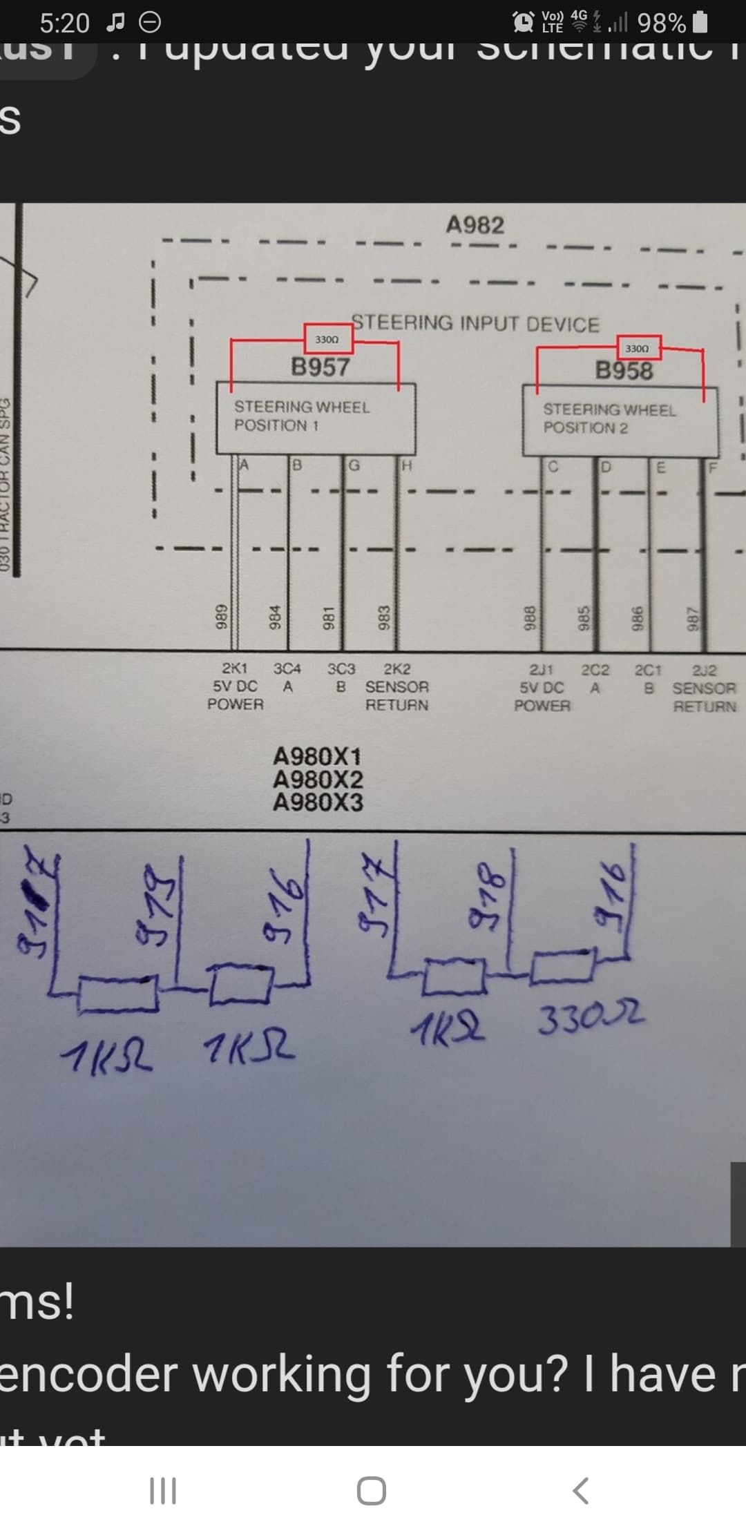
Yeah I have on a 9220. From memory it grounds the signal wires. On pcb v2 I removed the 12v feed from the encoder and ran 5v there the through a current limiting resistor. I cant remember what size resistor it was but it gave the same current as running 12v with the existing resistor. Cant remember how i hooked the singnal wire to the octocoupler. I’ll have a look later. Then I terminated the old sensor harness with some resistors like in the photo
Havent had time to play with this yet, but is the encoder powered with 12v as stock in the deeres? (What signal voltage is safe to use on the remote intput?)
Do you get a signal between GND and sig or +ve and sig?
Just trying to work out if I can try just piggy backing the signal wire leaving the factory SSU connected / code free (and working if needed)…Or if voltage will be to high, and what settings / pins other than stock “remote” intput id need to make it work…
The sensor runs on 5 volts. The signal wires are pulled to ground when the sensor is active
So should be safe to piggyback the sig and gnd into the PCB then and leave the stock system connected also / happy…
Struggling to get this to work with the AIO PCB, anyone else have any thoughts?
In an ideal world id like to just piggy back the signal wire and leave the OEM sytem connected to keep it code free!
You could just unplug the SSU. It’s typically mounted behind the cab on the back wall (on the outside). I just was looking at mine the other day, should have taken a picture of it. Also a pigtail goes from the SSU down to the back isobus plug that needs to be unplugged (it plugs in between the ISOBUS plug and the wire harness coming from the tractor). That will eliminate all codes and you can still plug it all back in if you wanted to use the Deere system in the future.
Of course it would be wonderful to reverse engineer enough of the SSU CAN protocol to control the SSU from AOG.
Hello JuanGiova
I am struggling with the Deere OEM Encoder.
So your solution for the arduino sounds very interresting.
What I’ve found of this SKF-Encoder are following infos:
Do you think it’s possible to adapt it to the teensy-code?
That would be a huge step forward to solve the problem.
Thanks for your help,
Greethings,
Peter
I guess I can review the teensy code to see how it works, I only use panda with teensy so I haven’t looked at it yet.
As for the JD encoders, the new ones are CANBUS, and I could never identify the brand, I know they are made in Mexico, nothing else.
If the teensy code has the same logic as the arduino, you can try the REMOTE, using the Signal-GND wires
My encoder isn’t CANBUS.
It is working with with an PWM signal. When you turn the steeringwheel, the pulsewidth changes. It changes in a 1/4 turn of the steeringwheel from 0% duty cycle to 100% duty cycle.
Now how can we get this into the teensy sketch?
Same as my encoder… But cant get it to work at the moment
#define SWEncoder  0          // Steering Wheel ENCODER Installed
#define pulseCountMax 3       // Switch off Autosteer after X Pulses from Steering wheel encoder

#define encAPin     2   //PD2 int0  Steering Wheel Encoder - turns Autosteer off

void setup()
{
  //keep pulled high and drag low to activate, noise free safe
  pinMode(encAPin, INPUT_PULLUP);
}

void loop()
{
 //Setup Interrupt -Steering Wheel encoder + SteerSwitchbutton
  attachInterrupt(digitalPinToInterrupt(encAPin), EncoderISR, FALLING);// Hardware IRQ 0

  interrupts();                      // Enable interrupts


	workSwitch = digitalRead(WORKSW_PIN);  // read work switch
    steerSwitch = steerEnable;  //take the Enable status as indicator of mode


   if (pulseCount >= pulseCountMax )
	   steerSwitch = 0; // from Steeringwheel encoder
       switchByte = 0;

}


//ISR Steering Wheel Encoder
  void EncoderISR()
  {
    #if (SWEncoder)
     if (digitalRead(encAPin)==0) // decide if external triggered
       {
         pulseCount++;
       }
    #endif
  }
This is the old code, from coffee track, now you just have to modify the PIN of the teensy you want to use and try if it detects the change when you move the steering wheel, if I’m not mistaken, it detects falls, that is, when you move, the PWM goes away to 100% and drops, that’s when it adds up ++
in teensy 4.1 all digital pins are interrupts, so we can try adding an interrupt to the REMOTE_PIN
attachInterrupt(digitalPinToInterrupt(REMOTE_PIN), EncoderFunc, FALLING);
Where would we need to try adding that in the code?
Encoder Library, for Measuring Quadarature Encoded Position or Rotation Signals
i use pin 12 for the A or B input of the signal encoder, you can try with that, just replace the ino
Autosteer.ino (25,5 KB)
Just tried this today, sadly dosnt seem to work, have got sig A output connected to input 12, (goes between 5v-0v with voltmeter when turning steering wheel), but AOG dosnt dissconnect autosteer…
Input 12 (A13, Teensy pin 27) is an auxiliary pin and not used in the Teensy ino anywhere. Connecting to that pin isn’t going to work without a teensy code edit.
I’m not sure that I see a good way for the AIO board to accept a 5v-0v encoder signal.
The Pres/Rem Input 10 is intended for disengaging autosteer, but with the jumper in the RemotePin position it looks like the optocoupler will always stay on, and the with the jumper in the PressureSense position you feed 5v to the Teensy pin (which cannot handle 5v inputs) and draw 22 ma from the encoder (should not exceed 20 ma).
So I’m not sure I see a good way to use the AIO board with the 5v-0v encoder signal. Hopefully we’ll figure it out soon. I’m watching closely, because my 8300 has the same encoder and I’m ready to tap into it too. I think its going to take some resistors.
What you should do for right now though is disconnect that signal from your board. You’re connecting a 5v signal to a Teensy pin that should not receive more than 3.3v.
You wouldn’t happen to know the SKF part number, would you? Maybe the encoder can run off 12v or 3.3v.
The encoder can run off 3.3v i think, its just I am trying to leave it Y’d, so the stock SSU remains on and happy with no codes.
I have changed the code to use input 12, and connected directly, I have use some resistors to make a voltage divider, testing on the bench using a 5v feed, I am not seeing more than 3.3v, and when I blip the wire on 12, it dissengages, so will try again in the tractor tomorrow