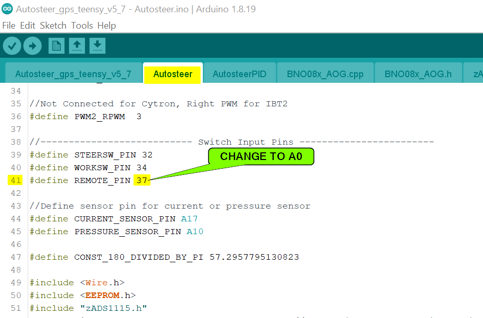
So ended up going back to original code (KISS!), but just changing the remote pin to use 26(A12) which is pin 11 in the ampseal… Then just used some resistors to make a voltage divider to get the signal voltage down below 3.3v, and it seems to work, havent actually been in the field yet, but autosteer seems to stay in, and setting the counts higher allows move movemen before it dissengages…
Im assuming this would work through the optocouper on the original pin if the 12v pullup was removed? Is this done via a resistor on the PCB or the optocoupler itself?
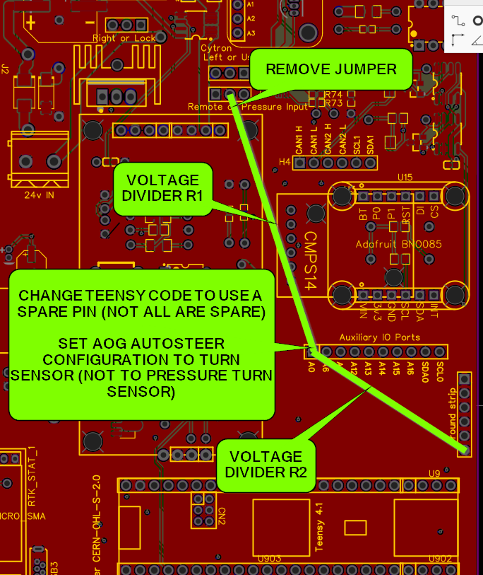
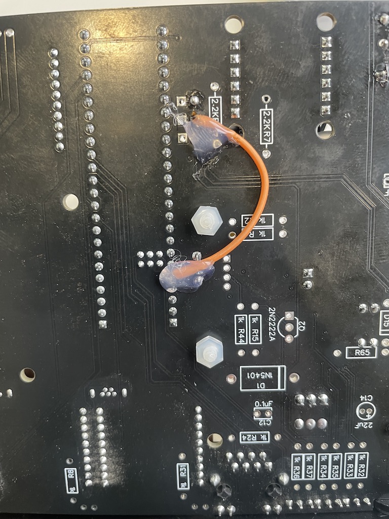
Have figured now how to use the original remote input on ampseal and have it working, I removed the pullup resistor between +12v and remote / pressure pin (150ohm located just above far left optocoupler), then theres a 8k resistor between there and the teensy pin, which I havent tested yet, but fairly sure that will work as currently using a 10k and well under 3.3v peak.
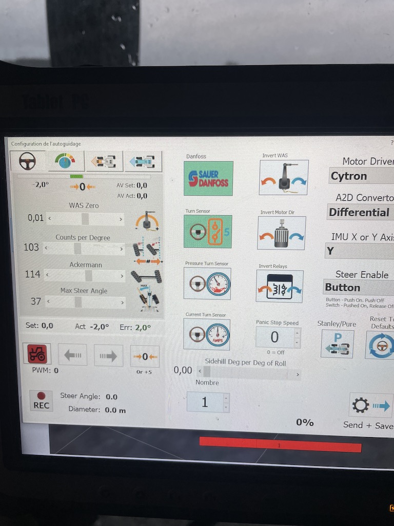
So basically no code change, jumper in pressure position, and add a resistor between the encoder output and the ampseal pin. Software wise obviously leave encoder mode on (not pressure). And set steps, will test in field hopefully later / this week.
Could you put a photo of the resistors that you removed, and what value is the resistor that you put in the encoder signal.
Would you be using a Digital input (Pin 37) from the teensy, but handling it as Analog in AOG, as if it were Pressure?
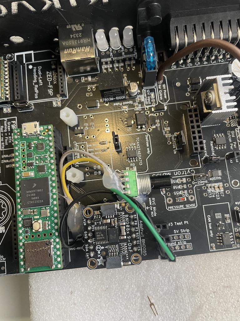
Here is my plan. It can be made with dupont jumper wires and is totally reversible/swappable to other boards. The Teensy will see anything above 2.31 volts as HIGH, so in lui of a better safety circuit its slightly safer to use equal value resistors, making the circuit safe up to a 7.2v input. 12v input to this circuit will harm the teensy.
Future versions of the AIO board will accommodate a 5v encoder.
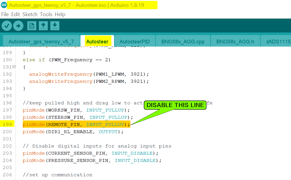
I changed the code… What you have shown above is exactly what I have done / explained in previous post… Works a treat…Just annoying as its not “stock” code, so has to be changed anytime firmware is updated
I’m not an hardware expert but I think It would be nice to be able to read a variable or “on/off” encoder, 0-5v pressure and 5-20ma pressure on the same pin with the same code.
Here is how I controlled a JD 7530 with Danfoss valve.
I was able to take the signal from the sensor in the steering column with this ino modified by @buched
works well with the addition of a potentiometer to reduce the voltage below 3.3 v
Signal - potentiometer - pin 22 teensy Autosteer_gps_teensy_v4_1_freq_v31 2.zip (46,6 Ko)
Have you found in bumpy fields you get some false trips? I found with mine i had to have it pretty high to stop it false tripping in bumpy conditions… Personally I felt like a x pulses per second option would be handy…so it auto resets every second or two to prevent positives from slowly adding up over time and eventually tripping the steering…