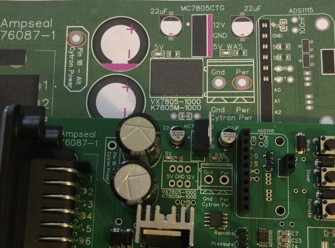
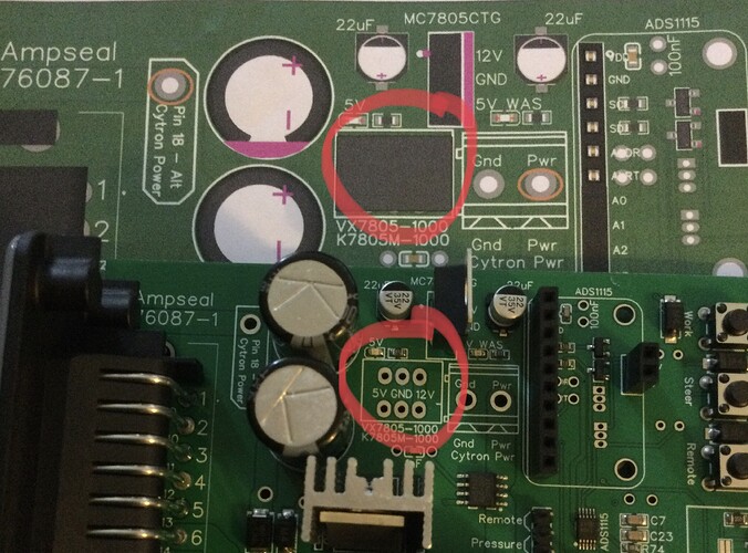
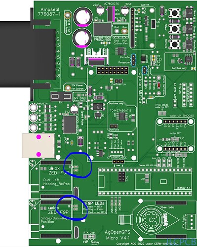
Just trying to get my AIO board working and found I had no power on 5v.
Looks like something missing on the board,any info on this part please.
The light for the autosteer will only go green when your moving, to get it to go green when stationery and to test your motor press the pwm button in the steer setup menu and you can use the arrows to test your motor .
Should’ve need to remove anything from the board to enable simulator mode
Looks like you have the capacitors missing. There is always a place to install these yourself via through hole components so look underneath the board for where they go, there not always next to where the surface mounted option is.
Just had another look and your missing alot of components, is this a blank pcb or a jlc assembled board
What is involved in using the canbus chip on a v4 board to read a factory fitted wheel angle sensor?
Hi! I composed an order with jlcpcb for the micro v4.1 pcb and luckily all the components are available! I am going ahead and place the order. Can you assist me with a list of other items needed to make the pcb fully functional. I mean the accompanying bill of materials in the zip file you made available is for components on the pcb itself. Its not the complete bill of materials to make the board fully functional? Can I ask your indulgence and point me to the rest of the bill of materials to make the board fully operational (excluding external components of course) and including preferred sources. Really appreciate the assistance. Thanks.
Needs custom code - at the moment, there are two version; CANBUS (where steering and wheel angle arrive over same) and “traditional” (where WAS and motor driving are analog).
I’ve a hybrid version where a traditional 5V WAS is used, and CANBUS is used to drive the Keya motor, but you need the other way round. It’s on the to-do list that you’ll be able to pick whichever way you want to go from a single code base tho.
Hi,
at first: the AIO v4.1 standard is great.
However I have few minor points to discuss for improvements:
-
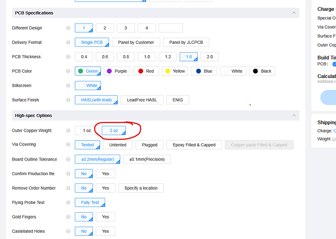
(more a tip:) If you order the PCB at JCPCB select (Outer Copper Weight = 2 oz)
Thicker copper means less heat, especally for the high current traces -
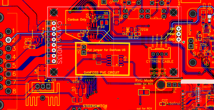
The routing of the WAS_H trace is dangerous!
The trace passes very close the motor driver output of the Cyton, which switches high currents (with low transient time = lot of high frequency components in the spectrum) which can incluence the quality of the WAS signal. From electromagnetic complience point of view, the cyton and the ADC should be as good separated from each other as possible. -
2-layer platine makes the design cheap, but is the most difficult to design. The problem here is that the the trances and the coresponding ground currents can not flow as close as possible to each other, since the gound plane is interrupted. A four layer PCB can be created more easy
-
for a better Ground potential at TOP and BOTTOM there should be much more vias connecting the ground area fills of both sides.
-
I don’t understand the function of R53 and C30. The inputs of the ADC are already high impedant. And for a low pass filter the order is wrong.
-
Further I would like to have an 12V-to-24V boost converter already included in the PCB. It’s not black magic. The from electromagnetic complience point of few it is less critical than the Cyton motor driver.
-
The mounting holes of the ADS1115 are smaller than all others. An M3 screw does not fit.
-
Next to all mounting holes there should be no traces (except ground). So it is possible to use screws directly without isolation rings. The coating of the PCB usally isiolates at first, but with time I creates a short due to the high vibrations. A ground protection ring with 1 mm or so around each monting hole would relaxe the problem.
This points shall just help to improve the great projekt and shall not be understood as critics.
Happy discussion!
I put together a testing guide for your new PCB4.1 (done on Micro) here: PCBV4.1 - build and test
I have now moved the jumper over to the remote side. I am now always have signal on remote. It does not matter if the autosteer is enabled or not. It does not matter if i’am moving / trying to move the steering wheel.
Some more tips?
How many counts have you ser remote off to?
Also measure that the pressure swit4change state, when you turn steering wheel, and make high pressure
It light up the led on the board, I have tried set it on 1 and 3.
How can i measure the pressure?
Adjust the screw at end of sensor.
Cytron Mod on V4 micro:
Team does the freewheel mod still work the same? Remove the 2 components (diode and resistor) and solder NC to the resistor pad. Does the other side of NC need to be connected to PWM2 on the Agopengps pcb ?
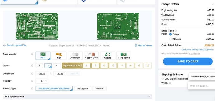
Hi all, I’m building my first board and opted for the V4.1 STD. I submitted the job to JLCPCB but noticed that it populated 2 layers. In the instructional video the V4.1 Micro has 4 layers. Is it correct that the STD version does only have 2 layers or have I messed something up.
Kind Regards
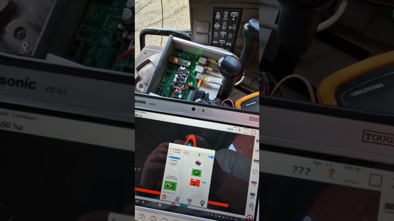
When i drive with my 4.1 micro board and loses RTK fix on one or both antennas. AgIO reports the GPS module as offline.
This can happen for example at the edge of the field where its trees close.
Is this wanted behavior or a bug?
Can it then be better with one GPS with a BNO085 instead of dual antenna?
Correct, V4.1 STD is 2 layer PCB.
Very much appreciated. Thank You ![]()
You might loose RTK near trees, but it would take close to a canopy of trees to loose GPS.
I had a new build loosing gps as well. Check the solder connections under the F9P’s. I had to wiggle mine to get it to stay connected when I found it.
Oh, and there is nothing better or more trouble free than Dual GPS.
The soldering looks good.
For me its always when the one of this two start alternating, i looses the GPS signal into AgIO.
I got told that alternating light there means that i lost RTK fix and have just RTK float. In the video i uploaded its the left antenna that is in float. I had RTK fix before
Edit: Video that shows my problems
