Recheck that you didn´t get wrong item like MC7808CTG
Be sure it’s not mounted backward and that it’s a 7805
If you really had 8v on the ads it is maybe dead.
it is welded the correct orientation and the reference is 7805
should this component be replaced?
if ADS is dead should it be replaced by another?
If you measure the voltage on the Ampseal 5Vwas pin, how much you have?
7805 is printed on the reg?
If you don’t have 5v there is definitively something wrong.
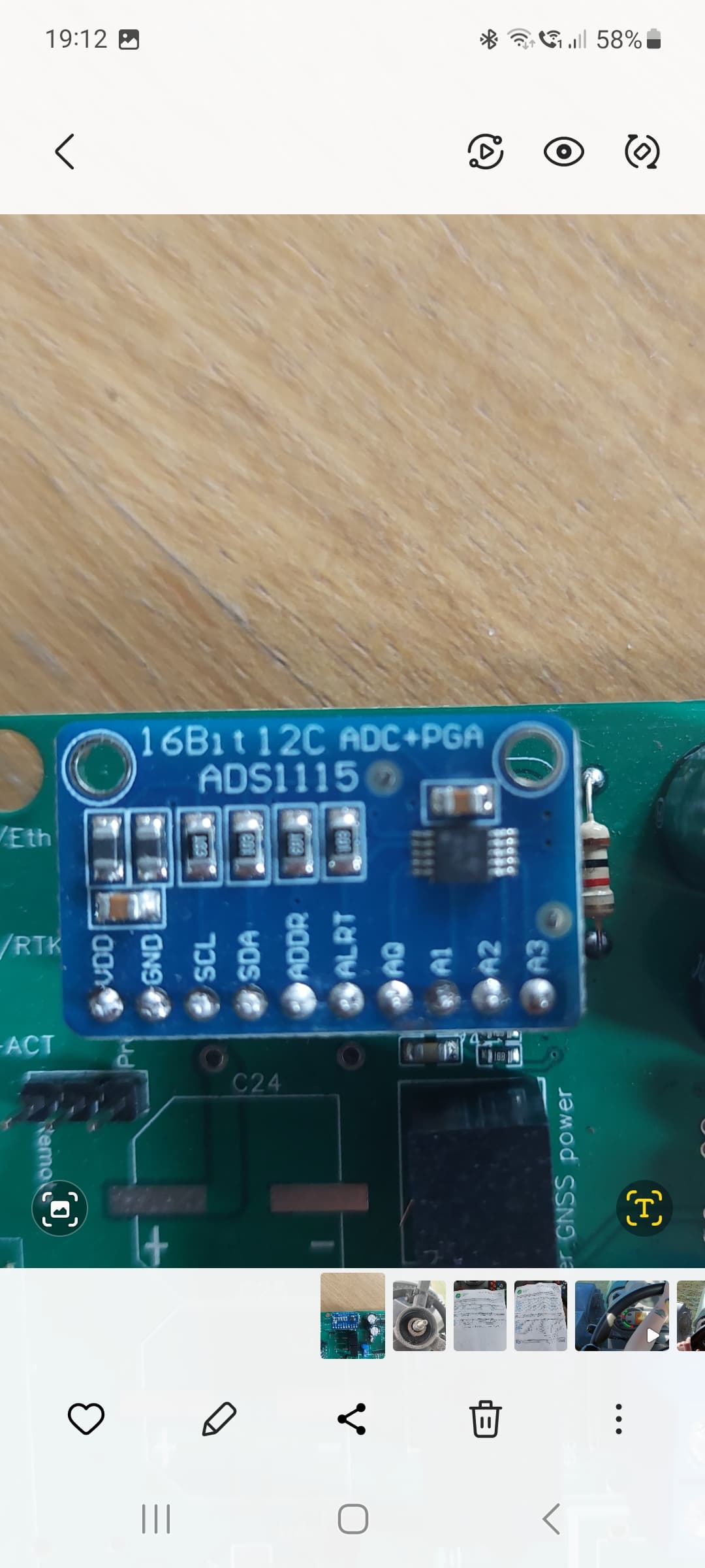
If it’s dead you can mount a little ADS1115 breakout board.
hello when will the PCB V4 standard come out? I’ve been waiting for some time, a bit impatiently and I don’t know whether to order v2.4 or wait for v4
Regards Oskar
5 Likes
Hi, would anyone have such a PCB V4 model for sale in Poland / Germany
hello guys, we are starting with our first pcb build project. i have the v4.1 micro boards here with ampseal connector ready to solder rails onto board etc. will be running the baraki hyd. valves if this works. can someone verify what pins you solder onto the md13s it loks like it needs a 2 by 8 set of pins at one end and a 1 by 3 at other end correct?
if doing hyd. steering valves does it need any other power jumper wires external on board or is that only for running extra power for steering wheel motors where more power is needed?
does someone have more pics of a finished micro 4.1 board with everything on it ?

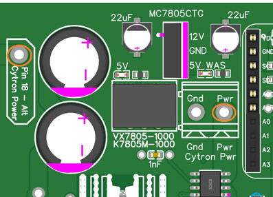
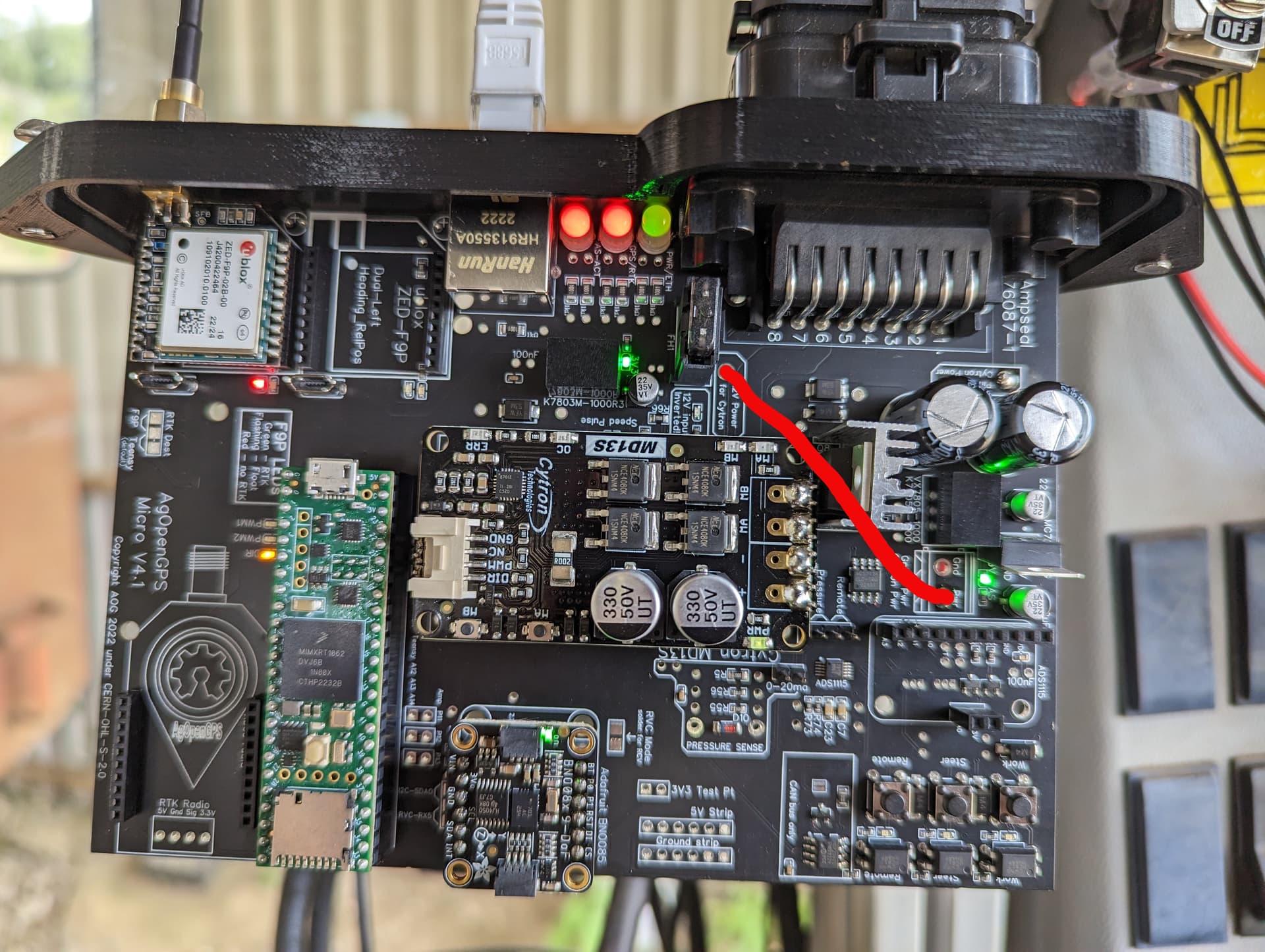
On the underside of the board I’ve soldered a jumper wire from the Pin18 hole to the Cytron power hole.
If using 12V hyd valve, you would solder a jumper wire from the hole labelled ‘12V Power for Cytron’ to the Cytron Power hole.
Thats all you need to do.
Like this:
You are correct for the Cytron you need two rows of 8 pins one end and a single 3 pin row the other.
That makes sense @TeddyStamford thanks . Cant wait to get this thing together☺️
Did you solve the 8v issue? I’m experiencing the same
Check to make sure the voltage regulators have the correct polarity. I had a few which where installed wrong and I got about 10v on the power rails. It isn’t clearly marked though.
Installed wrong by JLCPCB?
Yup. 3 out of 20 came that way. Think it was the one for the teensy as there was 10v on the teensy and it released a bit of magic smoke from the current sensor. Really hard to tell if they are correct as well because there aren’t any obvious markings. The one by the ADS1115 needs to use the outside set of pins but JLC put them in the inside one’s probably meant for the other type of regulator.
Maybe there is a 3d cap file for this project that can be ordered from JLCPCB? Thanks.
Anyword on the standard version?
1 Like
Im also waiting like a child… please some info ![]()
BGunics posted on the telegraph chat that they just got the standard boards in for testing.
1 Like
I wonder if anyone can help please.
I have ordered and received the v4 all in one micro board and getting all the other bits together. On my order there was one unselected part being :
U4
ADS1115IDGSR MSOP-10_L3.0-W3.0-P0.50-LS5.0-BL
I am not sure where the part should go or what it is for.
Can someone let me know what it is for and where to fit if it is required.
Many thanks
Sounds like analog to digital convertor… i believe teensey uses it to convert analog reading from wheel angle sensor to digital data… apparently newer aog versions wont work with analog data
Not sure on the newer micro v4.1 but the ads1115 is as said the analogue to digital converter i think. If this isn’t fitted by jlcpcb you can fit your own like this.
I had to fit one on my standard aio pcbs but I also needed to the 1k resistor you can see by the side but insure if its needed on the newer micro v4.1