Now im nore confused about all the powers lol i have 12v power to pin 20 and 22. Do any other pins need power or ground to test this?
Pin 20 is 12v OUT and it should not have any power connected to it. Pin 23 should be grounded and that is all you need.
sorry I didn’t realize the board had a fuse holder in it. What size fuse goes in there?
Ive got a 2amp in my board
Check your ampseal connections and diagrams, pin 22 is 12v in and pin 23 is 12v ground. Pin 20 is as said above 12v out
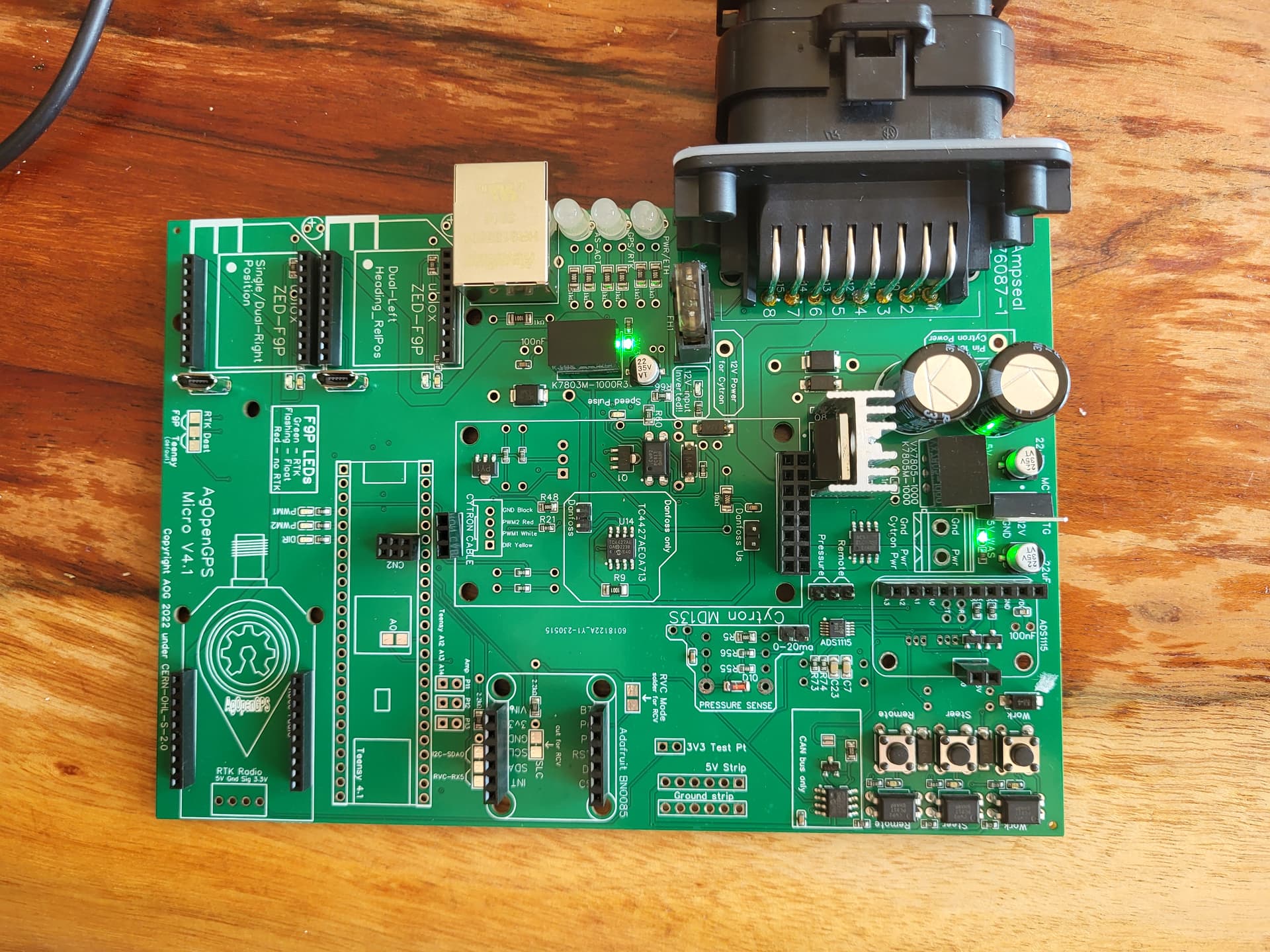
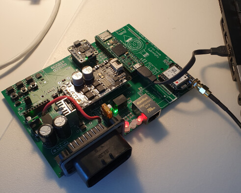
Hi Team. First time builder here. Can someone please tell me the purpose of the through hole component locations on the back side of the board? Are these supposed to be left empty or assembled ?
Thank you.
All of the through hole components on the back of the board are intended to be used as replacements for missing components. When you order through jlcpcb they will tell you which components are missing.
1 Like
Ah ok thank you for that. JLCPCB were just missing the ampseal. Excellent.
Is it possible to manually assemble the V4? I’ve uploaded the BOM to digikey, RS components and a couple of other places but they dont recognise the majority of components numbers unfortunately.
You’ll find the connectors for Ampseal here: Connectors · farmerbriantee/AgOpenGPS_Boards Wiki · GitHub
It is possible to manually assemble the boards but you would have to order a large number of parts and it would be rather difficult and time consuming. It is probably easiest to get jlc to assemble it and just solder on the amp seal by hand.
Hello, I’m currently doing the electrical testing of my v4 micro board and wondering about two things:
- The heatsink is not connected to gnd anymore right? (At least it is not axcording to multimeter check) My plan is to apply thermal paste and screw it to the mosfet, is that fine?
- all voltages seem fine, although the BNO vin is 0, so is the 3.3v pin. Am I missing something here?
Thanks!
Heat sink is okay. Do what you want.
There is no teensy on the board. 3.3 to bno comes from the teensy.
The 3.3v test point comes from the 3.3v regulator i think. Make sure you have voltage there without the teensy.
Great thanks, yes those are all fine.
I made the same mistake. Looking at the ampseal pin out picture pin 20 is mentioned as +12 board. I thought it ment that pin 20 powered the circuits and pin 22 the Cytron via a fuse. Looking at the table it clearly states +12v out. My mistake…The thing is that the board seems to work with pin 20 conneted to 12v!?
Still working on remote switch and GPS signal. Hopefully my problems is not caused by the inaccurate 12v connection.
GPS not connecting, need new ideas…
Prerequisites:
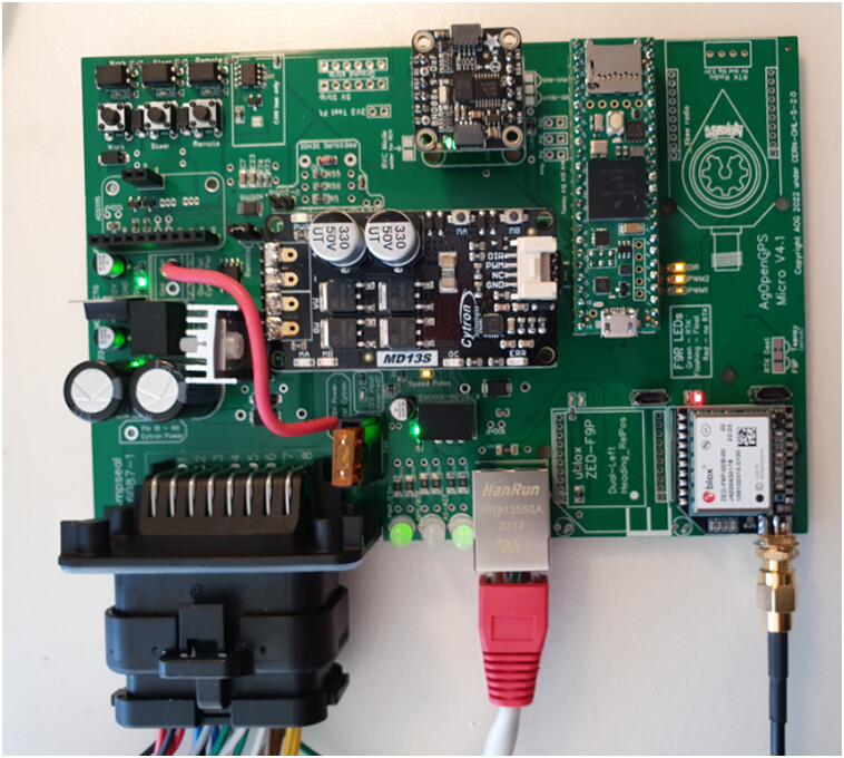
V4 micro All In One board, single antenna and IMU
Wire jumper for fused 12V power to Cytron
For the bench testing Ampseal connections are:
Pin 1,2 and 4 WAS (potentiometer)
Pin 5,6 DC-motor
Pin 7 LED ( connected to ground)
Pin 8 Momentary switch to ground
Pin22 +12V
Pin 21,23 0V (ground)
Extra: Added a none-conducting thermal pad and nylon screw to mosfet heatsink
Firmware for Teensy and F9P:
https://codeload.github.com/farmerbriantee/AgOpenGPS_Boards/zip/refs/heads/master
Teensy compiled with Arduino IDE 1.8.19 (have also tried to re-compile)
F9P new firmware and settings according to:
and yes, I remembered to save the config and I did set the baud in U-center to 460.800.
I have the Ublox antenna in the office window and U-center finds satellites
Tried NTRIP on and off
The AIO PCB seems to work fine in my other test except the remote steer switch (not on the PCB button either( have not looked into this function in detail))
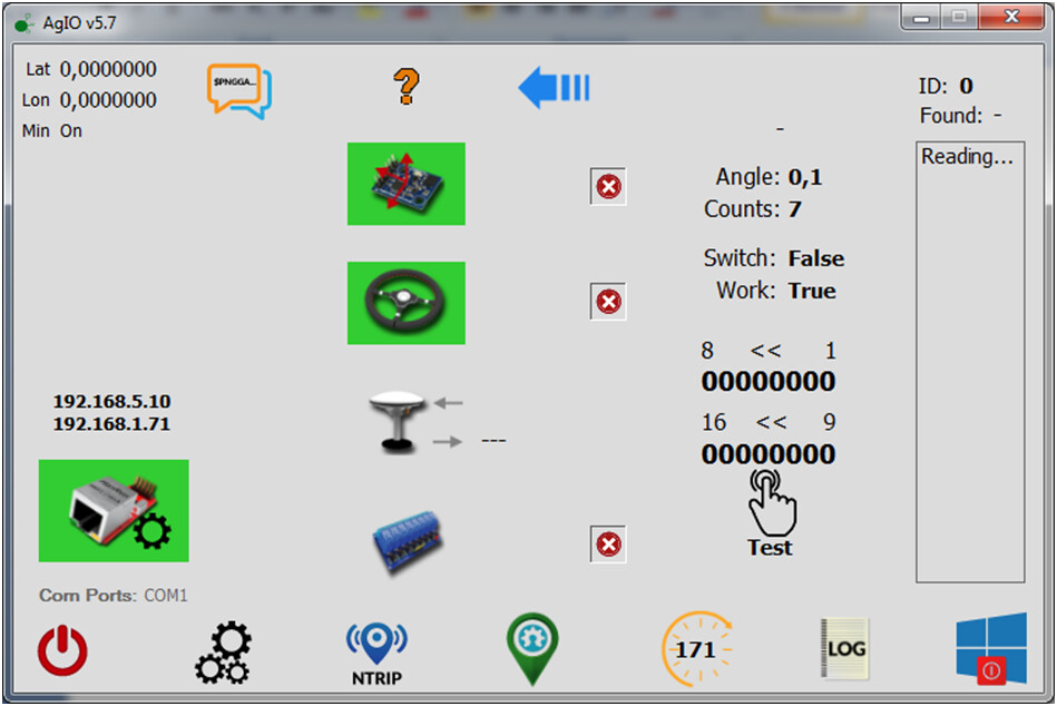
AIO running in simulation with autosteer, no green GPS LED ![]()
Mistakes made:
conntected 12V to pin 20
Compiled Teensy once when it was installed on PCB, but not when the 12V was connected.
Any help appreciated!
Edit:
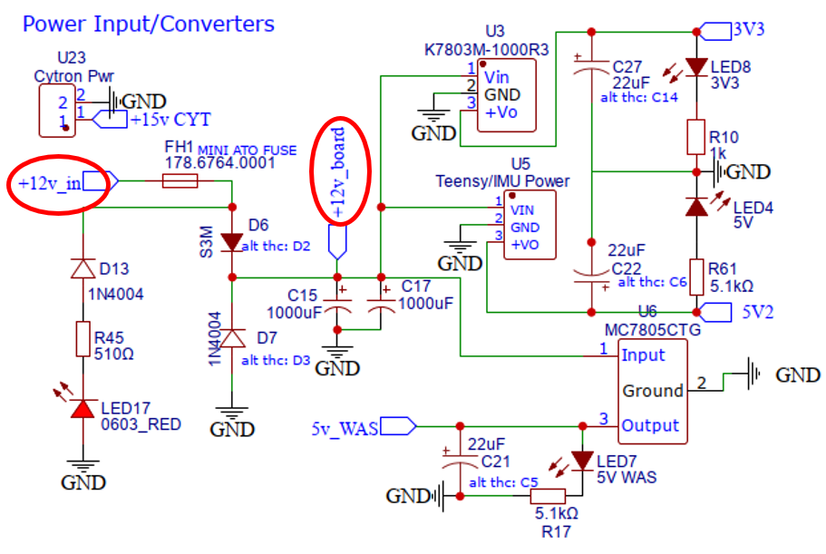
My mistake of connecting “+12V board” (pin 20) could probably not cause any damage. Looking at the schematic it is only diode D6 between the actual power supply.
Thank you very much for pointing this out. It all makes sense to me now and probably saved me from abandonning the project.
This is my first attempt at AgOpenGPS and it sent me on a wild goose chase
Does your GPS led light up red?
Are you getting GPS in AgIO not in Sim mode?
Could just be the led, sometimes they just need a little wiggle, if it works but no led.
Unlpug the ampseal and ethernet and connect the Teensy to USB, all three leds should light up red.
Thanks for the input.
Still just the two of them
In AOG it says I am lost and points to AgIO to fix it when I leave simulation mode.
When I compiled the Teensy I had to remove wire.h that was used for another project. Perhaps this was wrong. I am planning to install Arduino IDE fresh on another computer and give it a go…
You configure bautrate 460.800 or 460800?? There is a big differance
I meant 460800…