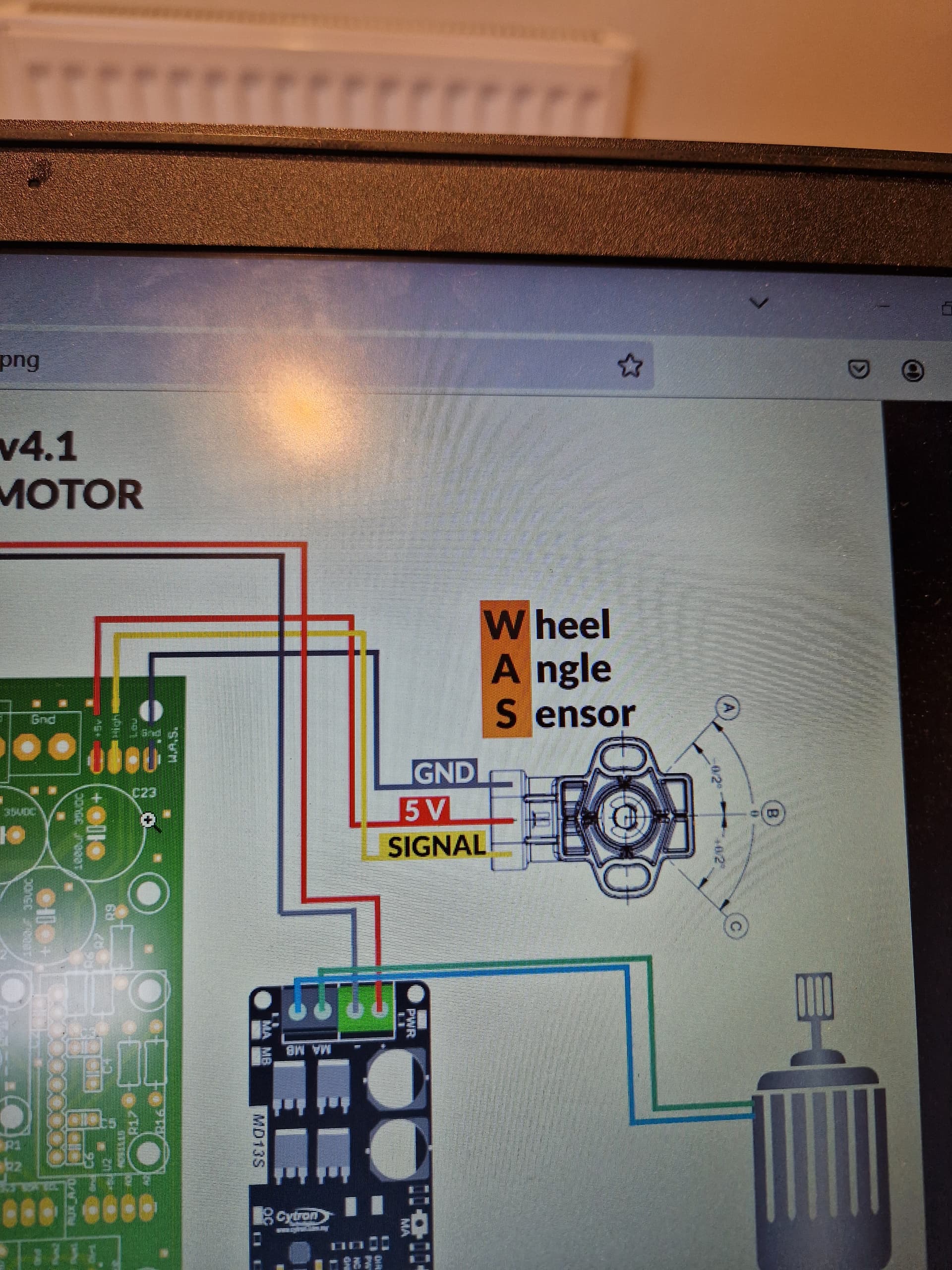
Im using a Land Rover Discovery WAS and ive wired it up as shown in the photo as thats all the documentation i could find.
Im not getting a signal from the sensor and the figure isnt changing on the screen.
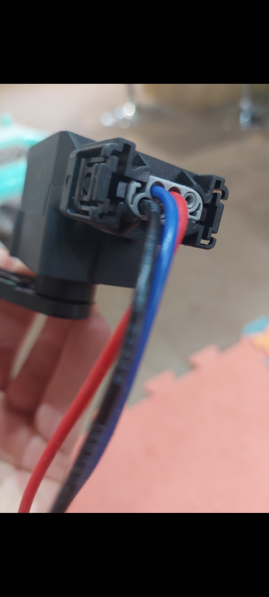
I then moved the Signal wire to Low from the High pin and the problem was not resolved, but i was then getting 5v from the WAS.
Any tips would be appreciated.
My next plan would be to change the WAS for a new one…
What pcb have you got?
Is there an ads1115 moduie or chip fitted to the pcb as this reads the was signal
You can test it with a multimeter and see if the sensor is working. There was recently talk of the plugs from eBay not being wired up right.
I have the AIO board.
Im not sure if the ads1115 is familiar to be honest, that could be it ![]()
Thanks @del_boy
I dont have one fitted! First ive heard of one!
Cheers ![]()
Maybe youtube how to pull the conductors out of the plug and put them in the right pins?
Some are surprising easy to get out when you know how
Put up a picture of your pcb might be able to help
No idea how to get pins out but im sure it can be done
This is what I did first time I got it and I thought it was broken.
Apparently you can’t get any readings from “hall effect” sensors it uses magnets instead of sliders like a basic pots, so u need to apply voltage for it to work.
What wiring did you use in the end?
Im getting 5v from Low but nothing from High.
Use this Landrover WAS - #5 by whiterose
1 Like
This is my PCB.
I dont have a ads1115 on the pins but im told the chip does the same job?
Is there any way of testing it to make sure its functioning?
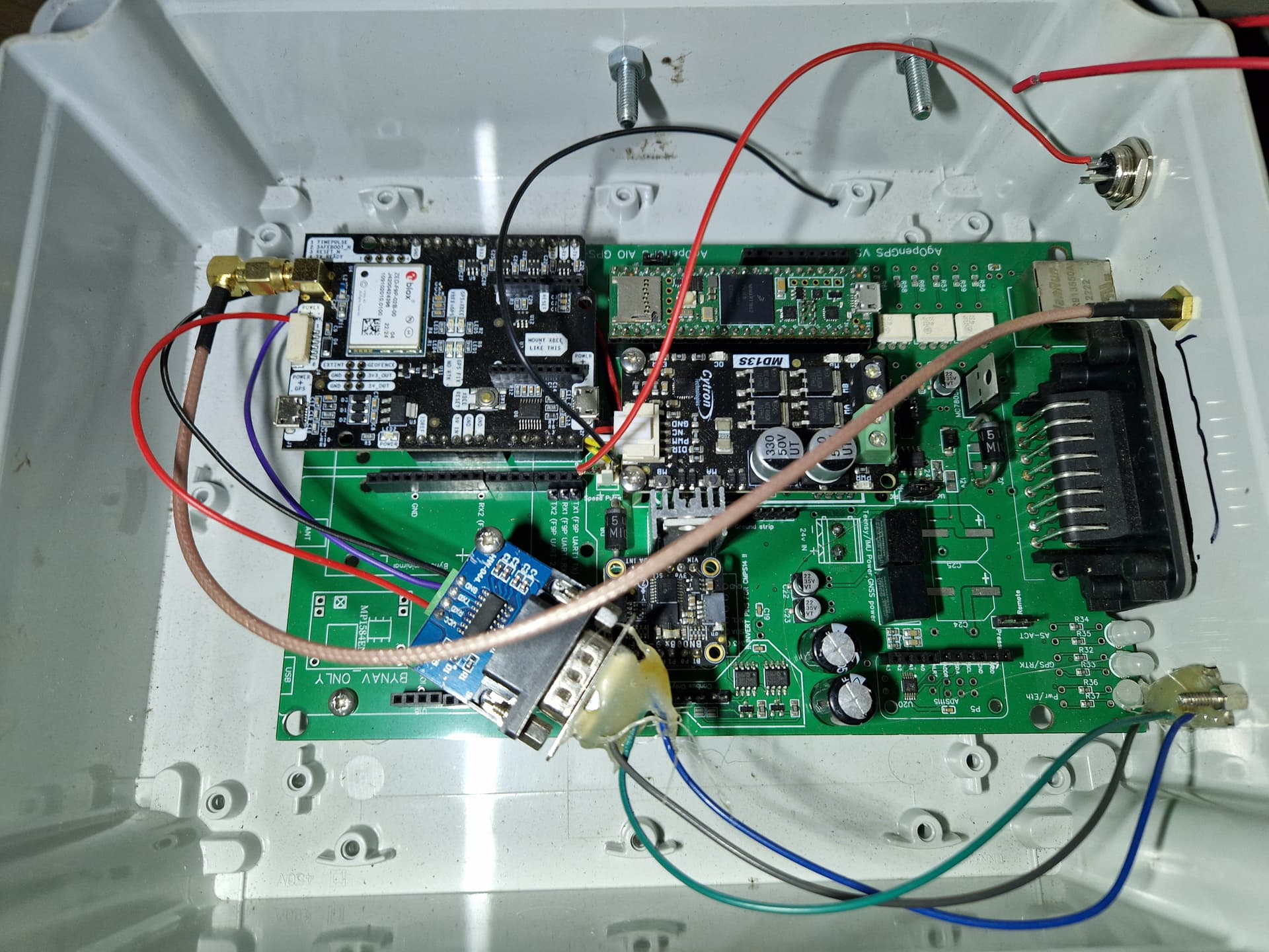
Take that extra ads1115 off to start with you have the chip installed on the pcb.
Whats all the extra wires about?
Was should be connected through the ampseal plug.
Theres a good chance that the wires In the was plug might be wrong as suggested in the posts above so check that aswell.
Have you flashed the teensy with the correct configuration files
Im using a Keya steering wheel, so ive flashed Teensy with the modified code (LED flashing as normal).
The extra wires from the centre are for speed output + - . I didnt realise you could take it from the AMPSEAL at the time.
The ones from the rear (left) are for rs232 connection to my Amazone sprayer.
Is the was wired into the ampseal plug aswell?
Does your aio pcb connect to the tablet ok via ethernet? Does all the lights on the different components light up
Is the was getting any power to it at all 5v
Yes, WAS is wired to AMPSEAL.
All the component lights are on and it connects fine except the WAS.
The screen shows 60 degrees, so when the autosteer kicks in, the wheel shoots off to hard lock.
Ill check to make sure the plug i bought is correct to start off with i think.
1 Like
There was always some confusion on which signal pins to use on the ampseal for the was high/low. Have you tried both ?
Have you been through the steer wizzard?
Is your was set up correctly. Should be reading 2.5v at cetre 5v full lock one way and 0v the opposite way? This can be inverted in the wizzard setup aswell
1 Like
So if i put 5v into Pin5 on the WAS, gnd to Pin1.
I should then be able to test the variable voltage across Signal (Pin4) and gnd?
Ive tried the wiring in every possible combination but no luck
Yes. That is correct. I can’t remember the pin numbers off the top of my head but hook up 5 volts and ground and test volts between signal wire and ground. On common plugs it is red wire for 5 volts, yellow or black for ground, and blue for signal.
Edit: yes those are the right pins.
1 Like
I think the main problem os that i dont have 5v across pin1 to pin4.
Im sure id have noticed this when i tested the board… whats happened?
Teensy is still blinking happily - i think thsts on 5v too?