AGopenGPS Hardware PCB Anleitung Bestellung SW

Und wo finde ich die PCB Daten (v4.5 Board) für die Bestellung?
Wenn ich das in die Suche eingebe komme ich immer nur auf das Forum, aber nie auf einen Link zu den Daten.

Und was ist die “PANDA” Version?
Ist das besser/neuer?

v4.5 uses PANDA

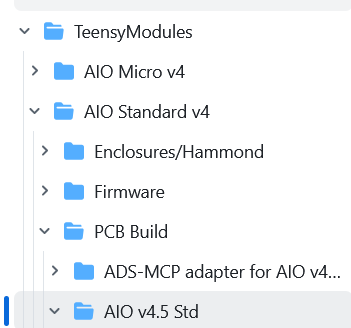
here you can find all for the Standard Board:
Boards/TeensyModules/AIO Standard v4 at main · AgHardware/Boards · GitHub

and all for the Micro Board see:
Boards/TeensyModules/AIO Micro v4 at main · AgHardware/Boards · GitHub

How do do order, see WIKI:
AIO Board flavours · AgHardware/Boards Wiki · GitHub

Thanks for your detailed links.
I was next to find the data, but was not able to. Now I am.
In the guideline to order the PCB there is mentioned 4 Layer board, but it seesm this version is 2 Layer only, right?

Is there also a description how to connect the motor or do i need to read the schematics and SW?

Micro PCB uses 4 Layer, Standard 2 Layer

hint:
read the Wiki carefully, you should find most you need to know,
Home · AgHardware/Boards Wiki · GitHub

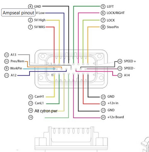
You will find the wiring example via “Ampenol 23 pin out” (use Table of Contents to navigate)

Variant with 12/24V Converter, see

AIO v4.5 update released - Hardware / PCB - AgOpenGPS

1 Like

Hello agian,

i got the PCB and assmebled hopefully all of the needed parts.
But beside the thousands of comments in the forum, i cannot find a guideline how to set it up that it is working.
Can anybody give me again support on this.

My status:

  • Board setup (with F9P, Cytron MD13S; BNO85; Tensy Board)
  • firmware flashed on tensy (Autosteer_gps_teensy_v4.ino115200.hex)
  • the FP9 was already flashed and worked before without the PCB v4.5 (dircet usb connection to AGopengps tablet)

now i do not know how to proceed.

  • Do i need now to connect by the LAN Socket to the PC or still with USB?
  • If USB, only to the tensy or also to the F9P?
  • what are then the settings for the AGopengps software to work (baudrate,…)?
  • do i need also the 6 Pins on the tensy or not (6 Pin “programming socket”)?
  • do i need to disconnect/cut the trace for tensy when i connect USB with 12v powered?

than


ks for your help.

1 Like

You need the 6 pins (2x3 socket) from the teensy for ethernet connection via LAN socket! I recommend using Ethernet.

Just for USB, connect Teensy only, there is no need to connect F9P too (because of Panda). It’s suggested to isolate USB Plug Power if teensy is powered from the board.

For the Ethernet, i need another Teensy version i think, becaus I do not have the needed Ethernet chip assembled. right? This take again some days to get.

What I do not understand that there is no guidleine how to do it right step by step.

What i need to conifgure within AGopengps when I use “Panda” with USB, because normally I have to use a seperate COM for Antenna, IMU, Steering. But now it should be only one COM POrt?

Your Teensy communicates via USB (Steering PNGs, PANDA (= GPS-Message + IMU Heading, IMU Roll)

Therefore You only need to select in AGIO your COM Port for Steer (=your Teensy USB Port)

image

Did you configure your F9P correctly with: Ublox F9P/1.13 SingleAntennaRover.txt ?

For Teensy & F9P there is also an Configuration tool availiable:

Thanks for the info.
Actually I am waiting for my new Teensy Board with the Ethernet option. Unfortunatley it is delayed.
What do i need to set there in AGopenGPS SW to work?

Did you order
Between Teensy and the Board you need the 2x3 connector: digikey

see Wiki:
05. Ethernet Setup · farmerbriantee/AgOpenGPS Wiki · GitHub

Now I have the new Teensy with Ethernet and the 2x3 Pin connected also.

Ang again i do not can find what SW for the Teensy is the right one. The one with 115200 Baud or the one without the 115200 Baud?
I nowhere can find the needed info.
Is this the baudrate communicating with F9P or with the UART to the PC.
If Uart with PC then it does not creates a issue.

Baudrate for RTK Signal is meant:

How do you get your RTK Signal? via SAPOS, APOS Dienst (use Standard 9600) via XBEE Radio (use 115200)

Hello again,
now I got most of the parts. Yesterday I had a first try and it worked, only some seetings I need to improve for drive wheel control reaction/behaviour.

One hting what I do see is, the GPS/RTK Led on the PCB is always red even i have RTK fix on the AGOPENGPS Software. What could that be?

I will later place all my leraned infomration here, that may somebody can get a benefit out of.
Form this point also many thanks to “wland” for strong support!

The meaning of GPS/RTK Led color is:

Red for single antenna,
Green for dual antenna setup

If you’re using a single setup red is ok.

Hello all,

now my system seems working.
Short summary what i did.
I ordered the PCBs at JLC due to the guideline: (small hint, directly order the Hammond enclosure cover also at JLC (topic comes below))

grafik
I used the standard one. Cost about 280€ for 5 pices (including Tax).
I only had 5 components what i had to order by myselfe. (They were not available directly at JLC).
It was a 5V LDO, the BNO0085 and a 5V DC/DC Module as well as the F9P and the Teensy 4.1.
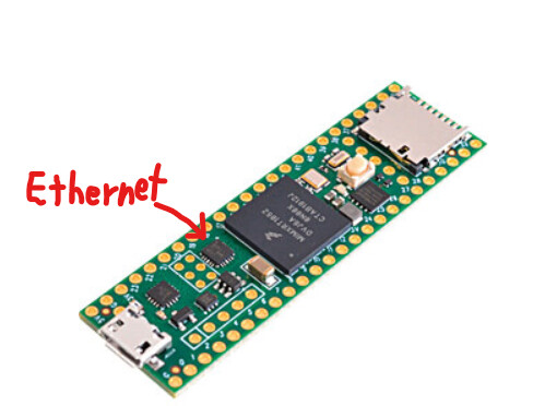
As hint: You need to order the Teensy 4.1 with Ethernet (the small marked chip needs to be assembled, there are versions with and without ethernet available)
(Consider also directly how to connect the 2x3Pin with 2mm pitch, i used a pin header soldered togeter, but this is not good solution, there are available conenctors and pins but i was not able to find them first)

grafik

Regarding BNO0085 i attached it in that way that the x axisx arrow is showing in driving direction. I glued it on the PCB in the right orientation, due to the fact i placed the PCB vertical. I do not know if it will work if attached in other directions.

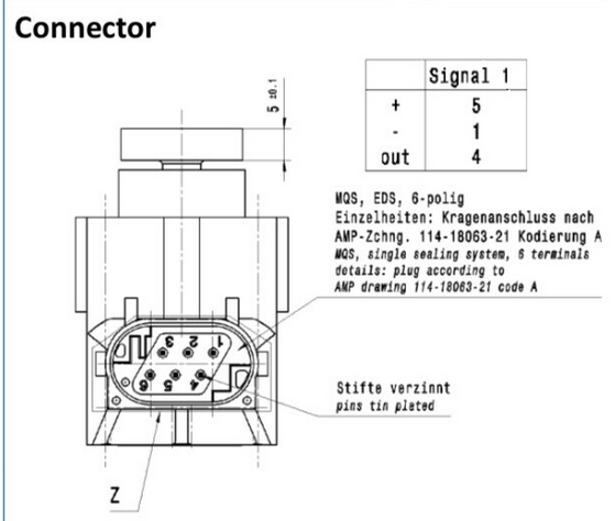
The Ampseal connector i baught at aliexpress (23Pin version with already attached crimped wires) (10€). (Number 770680-1)

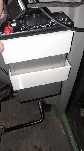
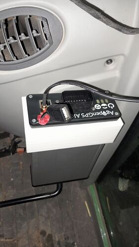
As enclosure i used the everywhere mentioned Hammond casing (1455Q2201).
For this i ordered also at JLC the Faceplate with the connector cutouts. See Link:

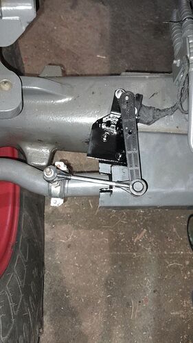
As wheel angle sensor (WAS) i used the RQH100030 (Landrover) from eBay. (~27€)
This can be directly connected to the Ampselconnector.
grafik

See Link for Ampseal pinning. (Hint: for WAS Sensor Pin 1= Supply, Pin 2 = Signal, Pin 4 = GND)

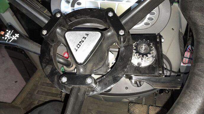
For my 312Vario i used self 3d Printed parts form this Link. Fits quite well. Only the screews need to be ordered due to the fact they are mostly not in standard portfolio.
Fit quite good. (Hint: you have to remove the Steering Wheel to assemble the gear)

Flashing was done with the available Tools. This i can describe in another message.

Hopefully i noted the most things.
Generally if I would by everything

Some pictures:


Again another question to the BNO085. Sometimes i read that the orientation does not matters, then I read again the Orientation is important.
CAn somebody give me a hint what is right.
Actually i placed the BNO in that orientation that the x axis (print on the BNO0085 PCB) is showing in forward direction and that the BNO0085 PCB is horizontal.
For that i had to remove it from the PCB due to the fact i mounted it vertical. But the question is if this is needed or not.

2nd sometimes i read that other boards uses a compass, does the v4.5 do not need a compass?

Thanks
BR

X → in forward direction, no roll inversion
X → in reverse direction, roll must be inverted

BNO PCB should be horizontal mounted in your tractor cabin.

2nd) you mean CMPS14 IMU module? This module choice will not longer supported in v4.5. It’s a former IMU module like the BNO00085.

Anoter Question, now I recognised that my teensy has a flashing light ( i cannot differ if it is red or orange), but is permanently flashing. Is this right?

Anf again regarding the roll and direction of BNO, it should be a postive angle shown on bottom right of the screen when hang to the right, or?

That means that the Teensy is receiving a valid GGA sentence from the receiver. If it isn’t flashing, you have a problem.

That’s right.