I achieved this with AOGConfigOmatic and the adapter. Make sure you have the correct cable.
I didn’t succeed on the first try.
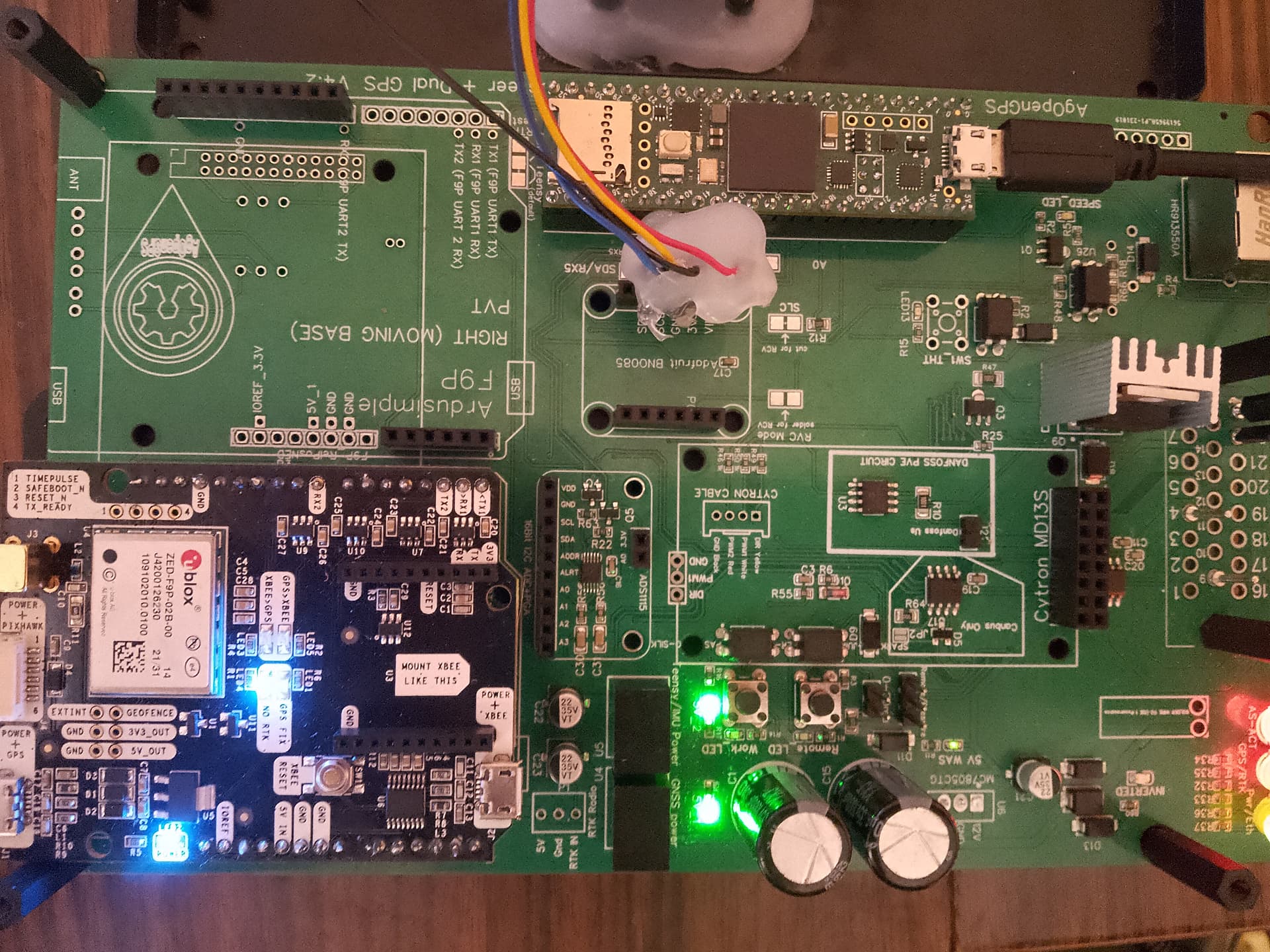
Too bad the f9p is longer and covers the micro usb.

That is not a F9P Micro. It looks like an RTK2B-Lite. It is larger as you found out and it has a different pin-out than the Micro.
Micro
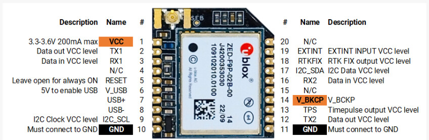
Lite
Thanks For the offer but I’m in the U.S. so not so simple. I’ll have to try with a different cable and then if that doesn’t work I’ll have to see where I could by the adapter you are talking about.
So is the correct board to order the micro board? It is so hard to find which exact components are recommended that I get pretty confused.
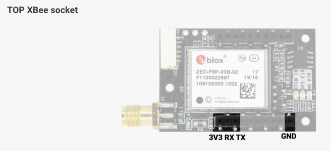
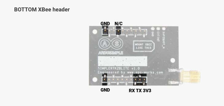
SimpleRTK2B Micro is for the board in your picture.
SimpleRTK2B Lite can work in a single antenna configuration. The power, ground and GPS data output pins are in the same place as the SimpleRTK2B Micro. However, the LEDS and the USB port on the PCB won’t work.
Thank you for clarifying that. I just looked at what other people had on their boards and ended up ordering the lite board. I will definitely use the Micro on other boards. I was able to get the Zed-F9P lite board programmed and functioning but I had to do all of the configuration through ublox u-center. Ag configomatic would not connect to it with the Xbee usb adapter that came with the zed-f9 lite. I first downgraded the firmware to 1.13 and then used the zed-f9 rover configuration file to get it configured properly. With this project I seem to have a knack for getting the wrong parts, learning how to do it wrong first before doing it right, and then finally figuring it out after reaching out. Thanks everyone for the help. This article helps walk you through how to program the zed-f9 without ag configo matic. If anyone is in the same boat as me. F9P firmware update and config files - Operations/Getting Started / How to - AgOpenGPS
How to wire a case tractor pressure sensor to this PCB?
Pin 1 and 4 for power and 10 for signal?
That isn’t a problem, it just means that the same part is used on multiple places on the board.
1 Like
Hi,
I have assembled the aio v4,5 board.
Juste one question left:
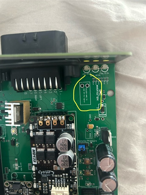
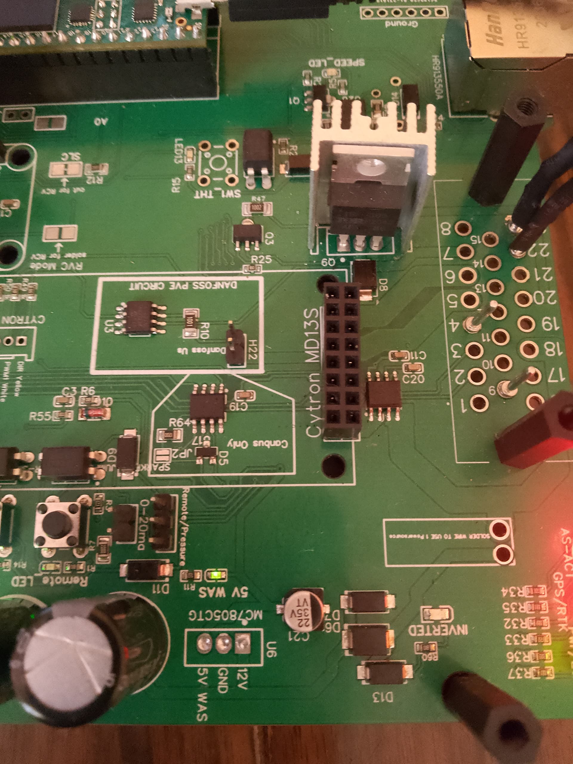
Do I have to solder a wire between the 2 holes to use a 12v motor? Traces are touching each other.
I supply 12v on pin 18
If no, for a 24v motor do I have to cut the trace and supply 24v from pin 18 ?
Thanks
If you are supplying either 12 or 24 volts to pin 18 no need to solder that. That it used if you want to power the motor directly from the 12 volt board power. Supplying the motor from pin 18 like you were planning is a better idea either way.
When you get the board there is no continuity between those two holes.
1 Like
Oke, and if I want to use a 24v converter, + 24v output in pin 18, and where do i fit the - 24v output? Or did I not need the - 24v output and can cytron just stay connected to the - of the 12v battery on the board?
Merci!
No need to do anything with the -24v. As you say it grounds through the board.
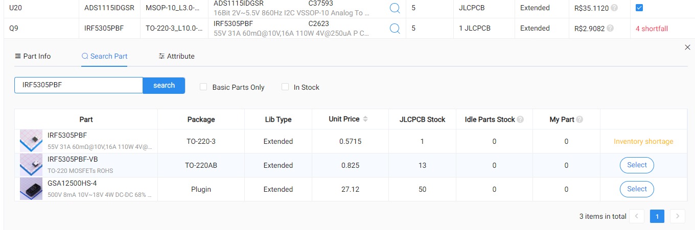
Hello, @m_elias, I want to order my v4.5 std PCB, but the mosfet is missing:
IRF5305PBF, and the JLCPCB is suggesting:
IRF5305PBF-VB, can it be used without problems?
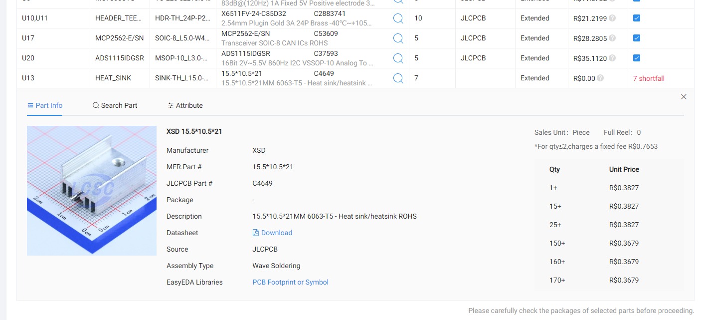
The heatsink for the mosfet is also missing, is there a replacement on the website?
And on the PCB part, do I leave everything default, or do I have to select something different?
1 Like
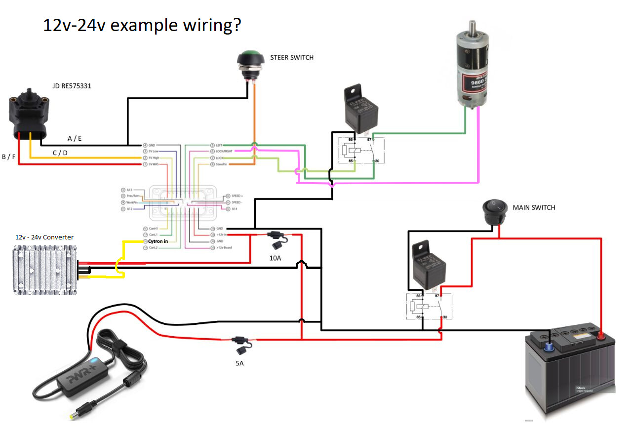
I’m a little confused as to where to stick the 12-24v convertor in this setup. Are you saying I should have it in my system like this?
1 Like
That is exactly how the 12->24v converter should go
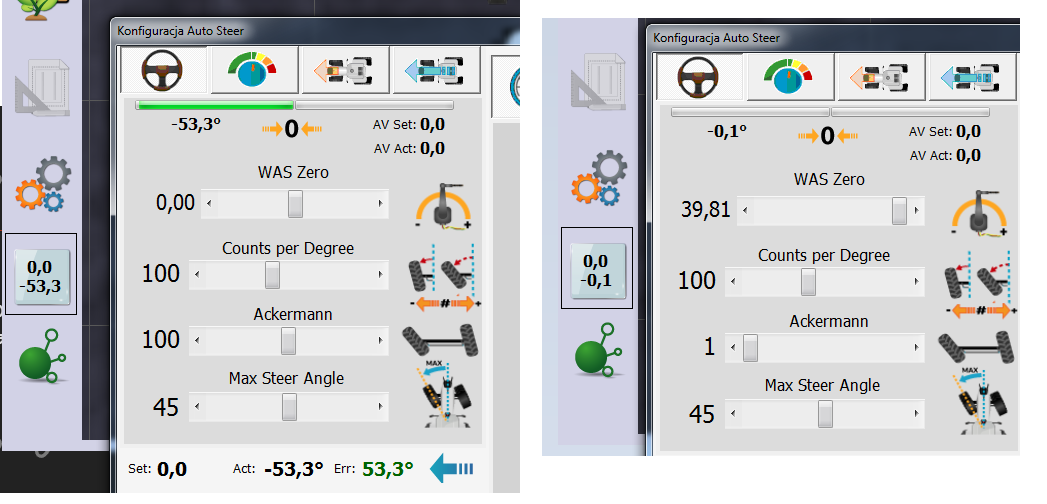
Hello, I have a problem with the autosteering module, I would like to have a button to activate the section, but at this stage I do not need autosteering, I am using the system for testing and visualization of the tractor in the field, so I do not have a citron and a steering sensor, when I soldered the power converters for the “L780SCV” steering sensor at the beginning of assembling the PCB, I encountered a problem that the wheels were turned in the program, I could not reset them in the program to make them straight I vomited the converters, but the autoster still turns on, the WAS power supply diode is lit green with a weak light, the output voltage is about 2.12 V, probably because the diode light is weak and the program still shows that the wheels are turned.
How to solve the problem of having a section switch but at the same time turning off the steering sensor so that the wheels are straight ?
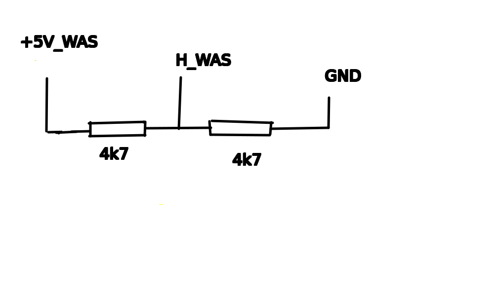
You are missing the WAS 5V regulator. If all you want to do is send AOG continuous fake WAS center data, I would do that in the firmware. But electrically, you need to use a 1:1 voltage divider from 5v or about 1:2 from 3.3v.
soo solder a power regulator for WAS, what should I do in the software in the sketch from Teensi or maybe in the setting of steering sensor I managed to set the steering angle sensor to -0.1 in the settings WAS zero to the right and Ackerman to the left the reading is not completely zero, can it be done differently?