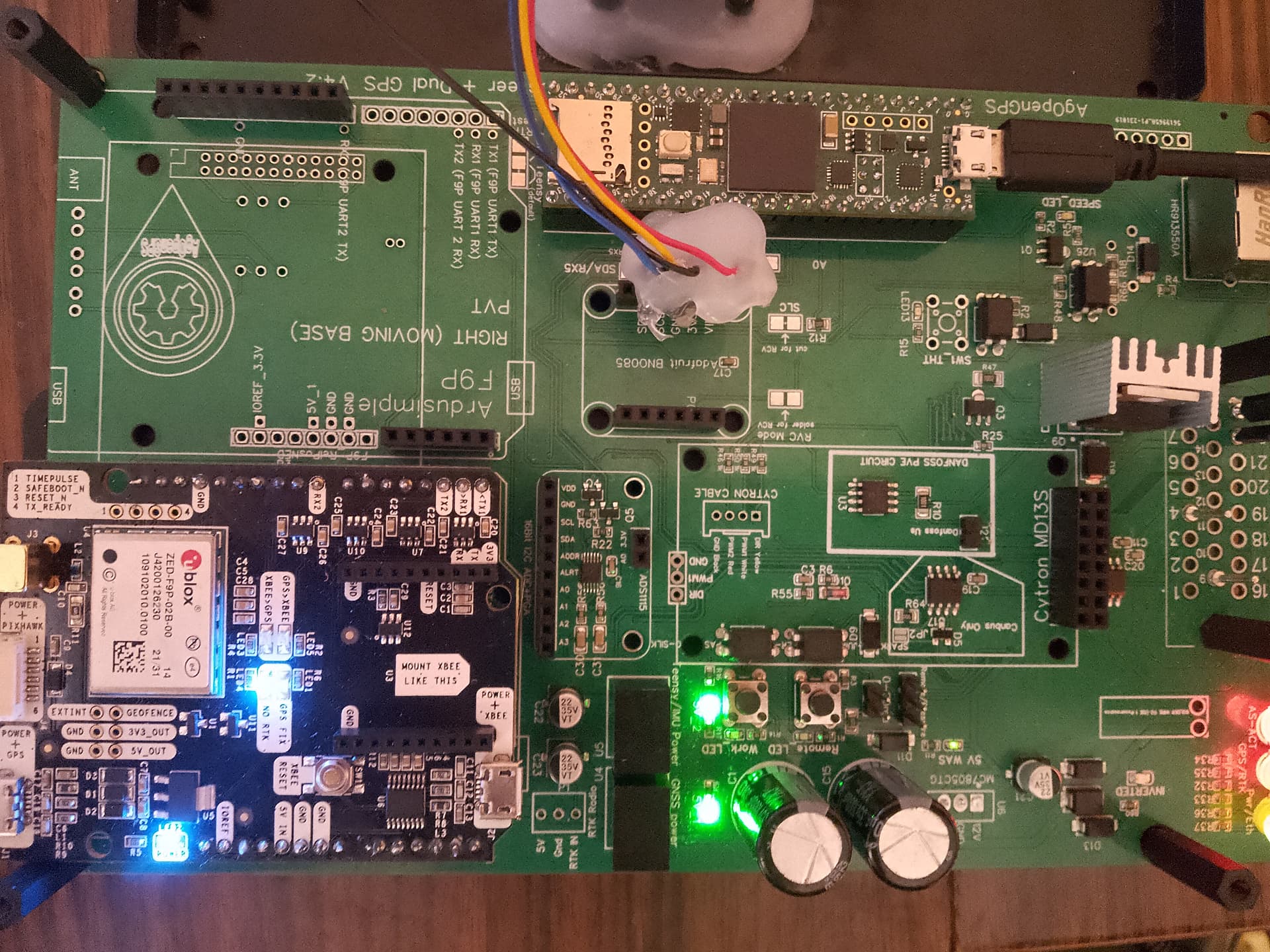
Hello, I have a problem with the autosteering module, I would like to have a button to activate the section, but at this stage I do not need autosteering, I am using the system for testing and visualization of the tractor in the field, so I do not have a citron and a steering sensor, when I soldered the power converters for the “L780SCV” steering sensor at the beginning of assembling the PCB, I encountered a problem that the wheels were turned in the program, I could not reset them in the program to make them straight I vomited the converters, but the autoster still turns on, the WAS power supply diode is lit green with a weak light, the output voltage is about 2.12 V, probably because the diode light is weak and the program still shows that the wheels are turned.
How to solve the problem of having a section switch but at the same time turning off the steering sensor so that the wheels are straight ?
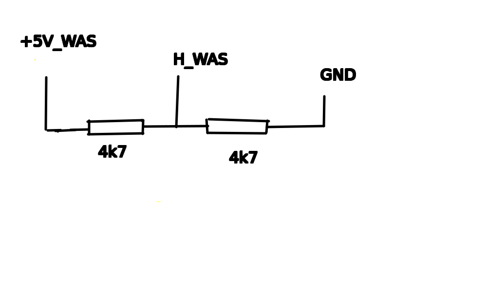
You are missing the WAS 5V regulator. If all you want to do is send AOG continuous fake WAS center data, I would do that in the firmware. But electrically, you need to use a 1:1 voltage divider from 5v or about 1:2 from 3.3v.
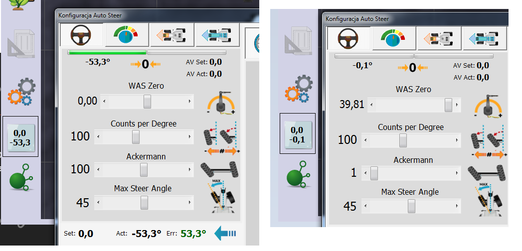
soo solder a power regulator for WAS, what should I do in the software in the sketch from Teensi or maybe in the setting of steering sensor I managed to set the steering angle sensor to -0.1 in the settings WAS zero to the right and Ackerman to the left the reading is not completely zero, can it be done differently?
If you’re just steering manually and mapping with a work switch, why do you need to display a zero angle?
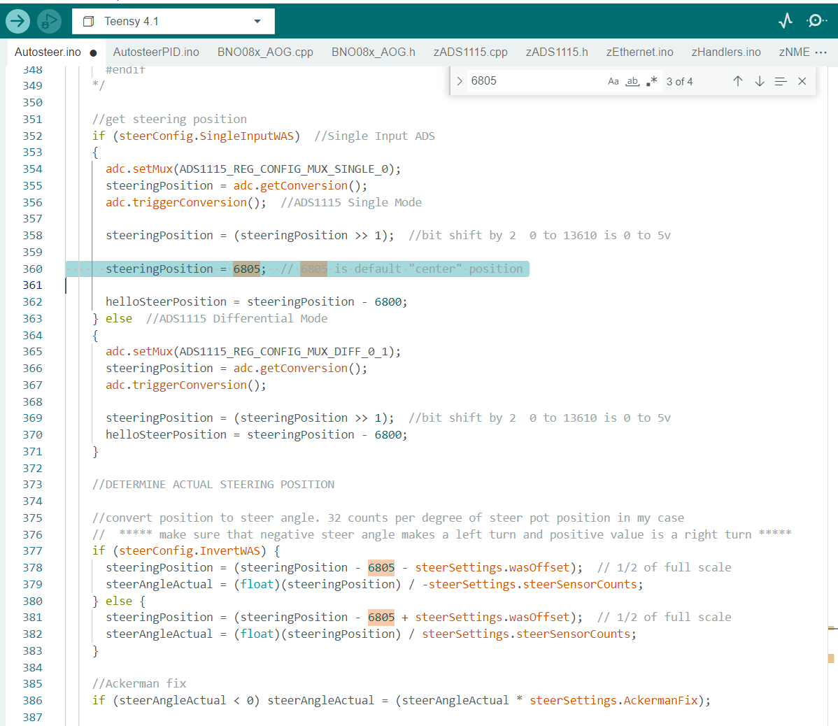
You could try adding this highlighted line. 6805 is the default “center” value when WAS Zero offset is set to 0.
I made two boards for myself and a neighbor. I encountered a problem - the tractor was driving sideways. BNO08 was set, corrected and configured, but it was still visible that the tractor was driving sideways. At the same time, my tractor had the same configured board without the autosteering module turned on. It worked normally. The differences between these boards were with autoster turned on, the wheels were turned 60 degrees to the left, I came to the conclusion that the problem may be the turned wheels, that the program thinks that the tractor is turning when in fact it is going straight
You solve problem?
If not , do you have identical setting on booth GPS receiver?
Same problem on mine one boards , tractor was driving sideways, no WAS problem , WAS working correct, problem was in wrong program in GPS receiver, I don’t now way.
I have RTK correction via Xbee and android lefebure NTRIP client.
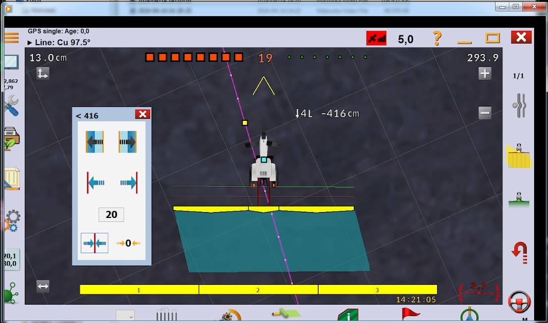
I’ll check it out and post a video

Do you have an IMU plugged in?
It is very possible the wheel angle causes your problem. AOG has a turning factor built in based off the wheel angle that adjusts the heading as you turn.
it works properly, you can see it in the video, and it was probably the fault of the fact that in the Teensy program there was no line of code responsible for the neutral setting as you linked earlier and the program simply thought that the PCB was sending it information that the wheels were turned
My final question is how can I turn off the control module in the Teensy code so that only GPS and IMU are turned on?
The old way was simply unplug the ads1115 but now that’s on the board so not possible.
The other solution is simply add “Autosteer_running = false” to roughly line 215 on the autosteer page where it checks the ADC connection
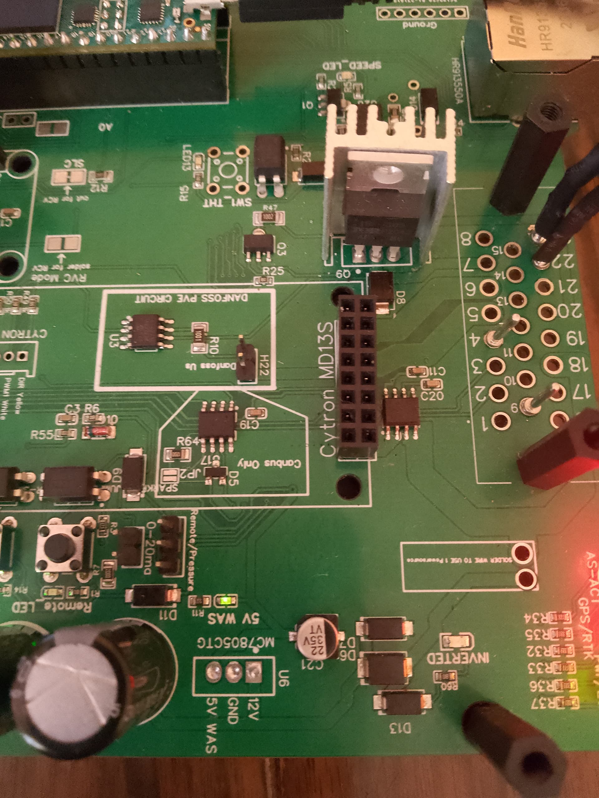
Could I suggest for future versions, that pin 18 be the exclusive way to power the Cytron.
The AIO PCB’s excluding the Cytron need about 0.5 amp to run, assuming using a relay to power any Lock valves via pin 7. So 1 amp fuse for most, or 3 amp if using the Lock mofset to operate a solenoid valve.
Yet often see installs with a 10 amp fuse protecting!? Pin 22 the incoming 12V+, can only assume they’re using it to power the Cytron too.
The other perhaps more important reason, is to be able so isolate the motor/valve whilst leaving the PCB powered up, yes you could do this after the PCB,but much better to do before.
I totally agree!
I don’t know what the future for the v4.x boards is but this winter I started a deluxe AIO design.
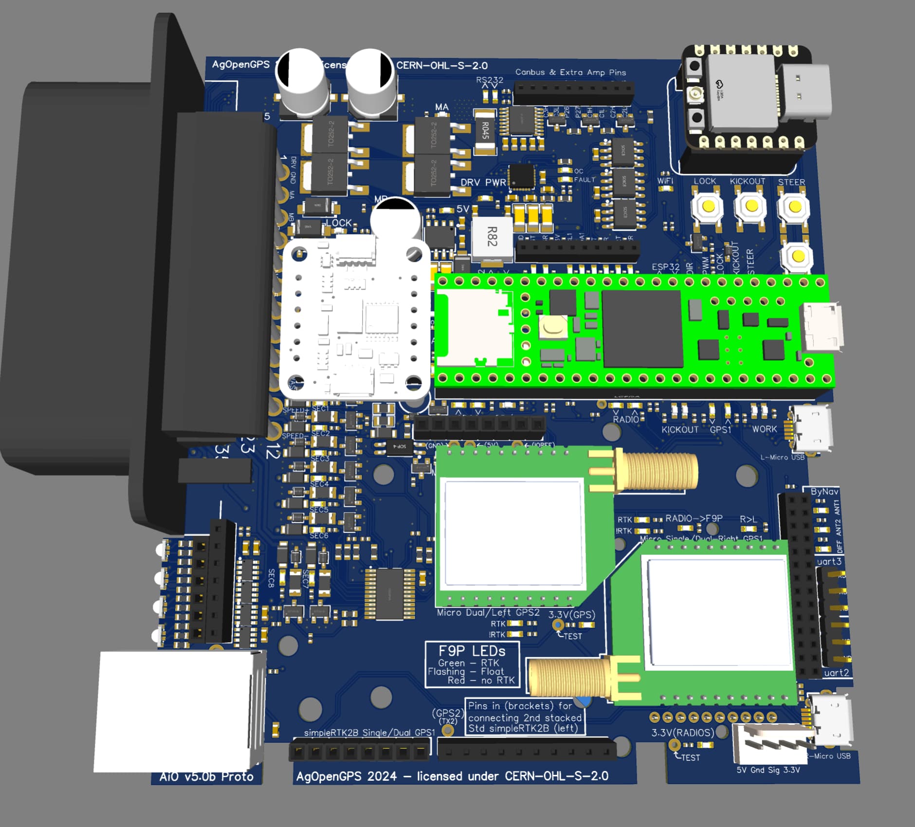
It’s the width of the Standard and the length of the Micro. Has on board cytron style driver, 8ch section/machine outputs, rs232, triple can bus, socket for Xiao ESP32 (for connecting Wifi machine boards etc), all USB ports point out the back, don’t need to cut Teensy USB 5V trace and uses the amp35 connector and costs about the same as the previous Micro. The motor/valve driver has it’s own dedicated ampseal pin.
That board looks sweet!
8 section outputs would cater for 90% of users I would imagine.
3 Can chips a big plus too!
very good
does it have a place for X-bee radio
There is a place for Xbee radio on the backside of the PCB.