Imu wants to be mounted flat. If you are certain thats how you want to mount the pcb ive read of people using 90* headers to re attach the bno. Its possible but easier to put by side of seat and running the wires through the side console next to it
LED 17, It don’t look right. ?
Diode, D13, It don’t look right.?
When is the LED_17 ON?
Regards
Put IMU on 4 wires and mount to side of box ideal bottom cover as you got more space there and will be oriented right (for your vertical install). Maybe try rvc mode. Then you can mount IMU far from pcb on serial cable. Then pcb can be in any orientation anywhere in cab.
With 90 deg heders you can put pcb like this. But still cant do vertical like you want.
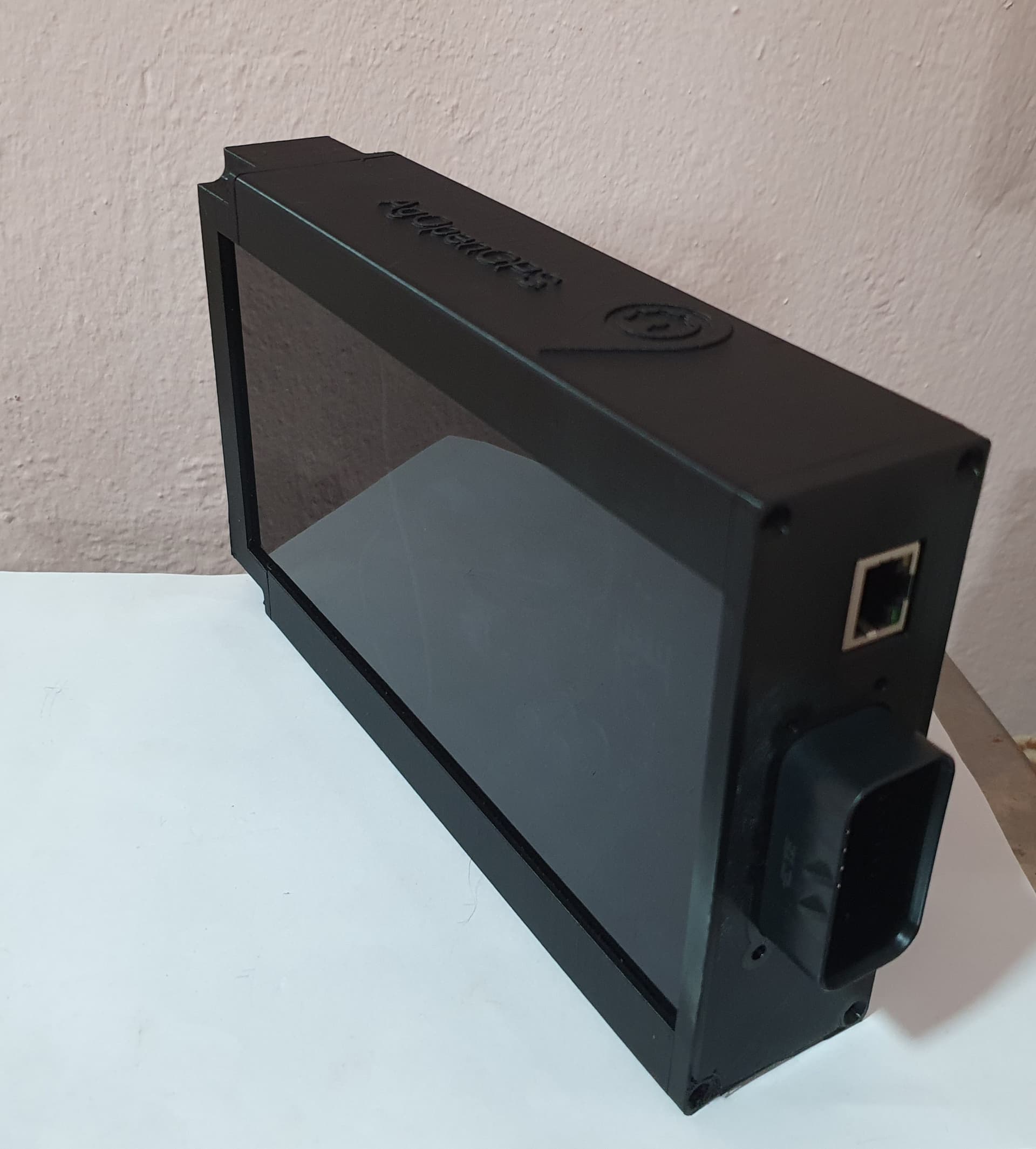
Is this printed box? Is stl avaliable? Thanks.
Are all v4 standard aio boards same dimensions?
Yes. Same dimensions with the v2’s and v3’s as well
1 Like
For the 3-wire pressure sensor, how to connect it?
signal pin 13
– pin 3
5v pin 2

I would like to use the oem steering sensor, but it is also used for front axle engagement.
Hey everyone,
I have a 4.5 STD and soldered everything like the wiki said, but I’m not sure if anything is missing, because I don’t understand the part with the jumper placement.
Would be great if someone can explain me where to put jumpers ( I want to steer with the Baraki Valve) and if I need to solder the 12V for Cytron.

1 Like

That’s the correct way to do it to cancel out any ground potential differences/noise. Make sure that the steering is set to differential in AOG.
You might be able to read the WAS over CANBUS instead, depends on the tractor.
Hello,
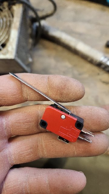
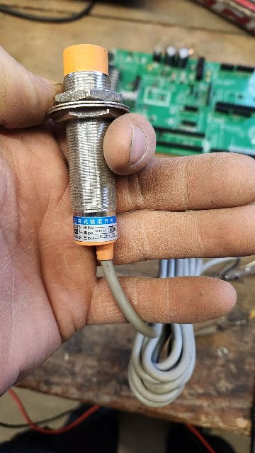
Got another question, I would like to wire up a works witch with a sensor so the paint and acres are more accurate.
Can I use this proxy switch, just not sure on the wiring.
Or do I have to use just a 2 wire sensor?
I see that I am also missing the 6 pins for the teensy. Are there some different length pins besides the normal header pins for all of the other boards? Or what is the correct way to get this connected to the 6 pins?

The wiring on the work switch is the same as steer switch. Anything that is a switch should work.
The way I did it was to solder another female socket like is on the board to the bottom of the teensy and then use male headers to connect the two sockets. Those are different kind of pins than all the other ones, closer together. I think there is a trick to do it by pulling regular pins out of their headers and soldering them in there but I’m not sure.
1 Like
They are a different length but there’s plenty of people who have pulled out normal header pins and soldierd them in . You have the block of 6 already in the board so that makes it easier to solder some long pins in if necessary
1 Like
Can some one explain why when I try to order my pcb that on the parts list I have odd numbers coming up for the quantity needed? I’m ordering 10 boards but it says I need 12 heat sinks, or 33 leds. It also won’t show the 3d rendering of the assembled board. Ive used the files listed above. I’ve tried 2 different. Browsers and computers.
Its got to do with minimum order quantities and how parts are loaded. Sometimes when you feed a real in you lose a few components so they still charge for that. Do you get at least the 2d renderings?