I have tested as much as I can think of and there doesnt seem to be a short that I can find.
I am wondering if this is a defect with my pcb? I cant understand what could draw so much power with nothing plugged into the pcb?
I have tested as much as I can think of and there doesnt seem to be a short that I can find.
I am wondering if this is a defect with my pcb? I cant understand what could draw so much power with nothing plugged into the pcb?
Maybe you could post a picture of your whole board. Are you powering it with the ampseal connector? There isn’t a short in the connector is there?
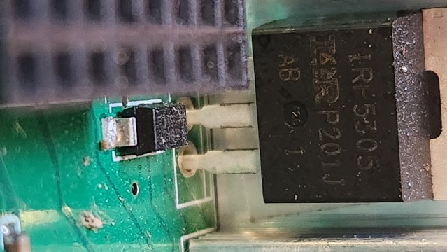
IF you are absolutely sure, the wiring and polarity is correct, then read the numbers and name of the mosfet. Wrong type could cause the burn. You can desolder the mosfet and leave it out if you intend to use motor and not hydraulic. (Would probably require the freewheeling mod on cytron) Freewheeling do not need hydraulic lock valves😀

thats the same one I used on my boards and it worked just fine.
I was thinking you should doublecheck you are putting 12 volts in through the 12 volt in pin and not through the lock pin. The lock pin is on the top row and the 12v in pin is right below it but on the bottom row (the one closer to the board). It could be possible to transpose them depending on how you look at the plug when you are wiring it.
pin 22 is the one you want. 20 is a low amp output. maybe check continuity between the wire you are suppling power in with and the solder joint for 12v in on the bottom of the board to make sure you havent transposed it with the lock pin
Pin 22 is 12V input and pin 20 is 12V output stabilized. So use pin 22 to connect 12V from tractor
Is it really stabilised? Or just return tractors 12v that can be used for something, up to 1A.
Yes, there should be a view of the PCB with the components.
91€ for 5 micro PCB including 2 assembled
Thanks for the help, I am definitely struggling with this.
I am using a low powered power supply now so I hopefully don’t burn up another pcb.
Right now I have nothing but 12v and ground pin 22 and 23.
I have power on both sides of the FET, see pic.
Is that correct?
Here is a picture with everything but the gps on. I don’t want to power the gps with out the antenna on.
I am getting one solid green light but no flashing lights on the ethernet plug, I’m thinking it needs gps fix before it starts communicating?
Also no lights on the teensy is this also cus the gps isn’t installed?
You don’t have the 6 ethernet pins in the teensy thats why its not communicating
i powered up a good board I have and yes, power on both the pins you indicated.
Yes, the teensy will not flash without gps.
Looks like the green light on the ethernet port should light. Llike del_boy says you need to solder the 6 tiny pins for ethernet on the teensy.
Thanks guys, Im making progress!
So the next problem I have come across is the gps doesnt seem to be talking, I can see my steer and IMU but nothing in the GPS.
So I am using adrusimple from the PCB V2 where I had a USB cable sending the info, is there a setting in U-center that i need to change sending the GPS to a Different location? a uart or whatever? I dont really want to just flash the ardusimple to because i am using the X-bee radio and it was some other settting that I dont want to mess with. (i set up the Xbee 3 years ago and dont really remember)
Am I suppose to short the pads that go to teensy?
More progress,
Well I Just flashing the F9p, and that fixed my communication problem, so everything is working now its just time to clean up the wires.
Thanks for all the help
The pads to the Teensy are shorted by default. You don’t have to do anything.