What I mean is, in AOG you need to send steer config and steer settings to the steer module so that it knows what counts per degree and switch or button mode.
I did go through the steer wizard if that is what you are wondering.
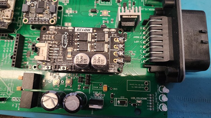
Really? Then why there a spot for it on the pcb?
Don’t mean to question you, just trying to finger this all out.
Also I was wondering if, on my pcb v2 we used that automotive relay to cute the power to the pcb.
Is that not a thing any more in the v4. 5 pcb?
In case the smd one isn’t available. I think most components are that way, you can solder a replacement if you need to.
Another question,
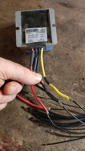
I’m using the 24v converter so I put 12v to 12v in, then take 12v out pin to the converter, then the 24v on the out from the converter to the cut-in pin,
Can they all comen ground? Seems odd the put the 24v ground with the 12v grounds?
The converter needs more amps than the 12 volt out pin can give. Just supply the converter from the main 12 v coming from the tractor. If you are using the 24 volt converter most people use it is common ground anyway. No need to do anything with the 24 volt ground. Just bring +24 volts in to the appropriate pin
You have to use common GND, on the cytron the power GND and the signal GND are connected.
Yes. If you test them there is continuity between them. They are just connected to the same place inside the converter. You really only need to hook up one but the way you have it wont hurt anything.
Hello,
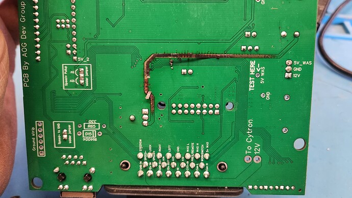
I am in the process of powering the v4. 5 for the first time and had a puff of smoke.
Can some one help in to figure out what power is moving between the capacitor (I believe) and that part on the heat sink?
Bugger. Did you follow this link for step by step testing? There was problems sometimes with jlcpcb assembling components wrong and then cooking the f9p at one point. This was why the step by step guide was created on powering up
Are you 100% sure your amp23 connections are correct? It looks like the Lock output FET is involved with that trace burning.
So I did some digging,
I removed all the controllers, and the 24v convertter,
Its just the ampseal plug and wires and a power plug
I put 12v to the 12v in pin and another smoke show.
I tested with my ohm meter and nothing seems to be shorting out.
You mentioned the lock pin and I do have contanauity between the lock pin on the ampseal and the middle pin of that (relay?) on the heat sink. I do not have anything connected to that lock pin on the ampseal
What is this trace that I burned for?
The trace your burnt supplies power to the lock circuit. Did the heatsink short to anything?
Lock circuit? I’m wondering if this is something I am not using?
The fet(the part attached to the heatsink) appears to have burned as well. You don’t necessarily need the lock circuit unless you have hydraulic steering
I am in the process of ordering AIO v4.5 Std.
I replaced C459134 with C409522.
The problem is that heat sink C4649 is also in shortfall.
Can I add this missing heat sink myself later, or is there an alternative available?
Thank you.
EDIT: how about C116600? It is 15x10.5x21 and C4649 is 15.5x10.5x21
You can easily add the heatsink later or you might not even need it
I checked the github and C116600 is ok.
How about part placement. After clicking next, there should be 3d rendering of the final assembled board with components? Yes or no? It shows only the board, no components on board, like in the video on YT I followed.
https://www.youtube.com/watch?v=nFtups0Z6I8 at 4:00 minute.
Sorry for silly question, but I am ordering first time and would like not to screw something up. ![]()
It is about 95 euros without shipping and Customs duties & taxes. Does that seem ok?


