These cheap-crap Amazon cameras are superb! This is in a pitch dark room! I don’t have to leave the sofa! ![]()
PETG working nicely now at much lower temps than they should be. This is on an ender 3 V2 neo.
These cheap-crap Amazon cameras are superb! This is in a pitch dark room! I don’t have to leave the sofa! ![]()
PETG working nicely now at much lower temps than they should be. This is on an ender 3 V2 neo.
which camera are you using? Does it have IR lights on the front of it?
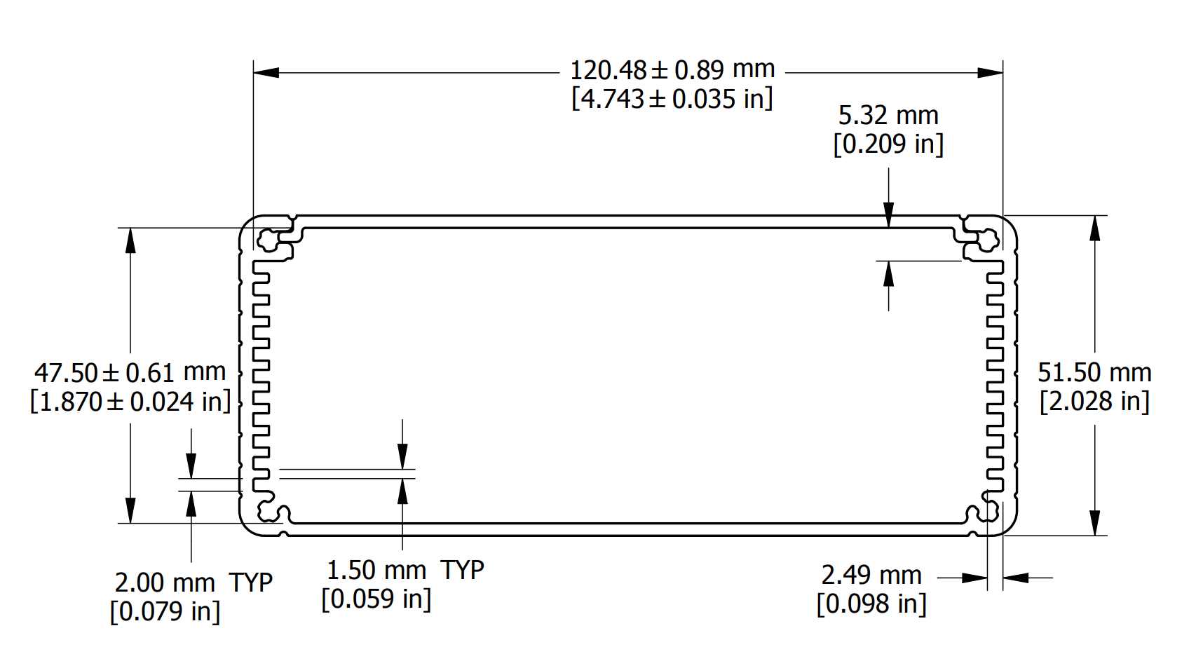
@Vili do you have a 3D CAD (.step for example) model of the assembled PCB V2.4 Standard with Ampseal connector?
I would like to design custom end plates for a hammond box (1455Q2201BK seems to fit, see drawing below). In order to draw the holes in the right place, it would be great to have a 3D CAD model of the assembled board. I was not able to extract such a model from easyEDA. When I export a 3D model from easyEDA, it is not to scale.
1455Q2201Cover.pdf (58,9 KB)
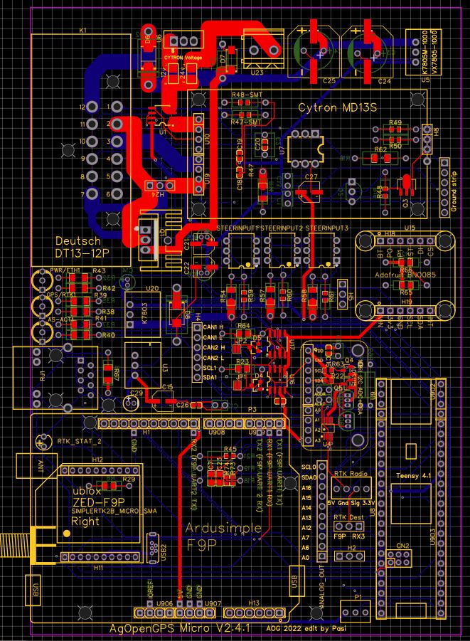
I edited for myself. Micro and Deutsch. Short 4mm copper +12V_in, Lock, Right, Left etc… One normal F9P or ZED-F9P. I hope I did it right and it works.
Looks good. That is similar to what we are doing with the all in one boards.
I would put the xbee socket back on the board though. If you run a micro, and want to use radio corrections, you won’t be able to very easy.
Hello,
I received my standard f9p pcbs with ampseal 23 and I’m starting to look at how I’m going to make the modification for the high power part.
In order to keep the stability of the cytron I still think of soldering the pins on the power input and output side in addition to the two screw terminals.
From my observations this should pose no problem since I keep the same pin on the ampseal.?
For my 6/2 valve which consumes 36w under 12v so 3A wouldn’t it be wiser to connect a standard 12v 40A relay between the lock output and the valve.?
Thanks
Good idea keeps min amps on the board
Unfortunately PWM2 triggers “lock” often around 0 %, thats the reason why a Mosfet is used.
Or better adjust code and use A14 as 5v output when engage button is pushed
Hello, thank you.
The idea of the 12v automotive relay reassures me more than using a “Chinese” 5v relay as can be used with the Arduino for example. These 12v relays are reliable and proven for many years. ![]()
I don’t quite understand the story of the lock around 0%… ![]()
![]()
![]()
![]()
The butt is not to bypass the MOSFET using the PWM2 output to directly power the 12v relay BUT to use the MOSFET output to operate the relay.
My knowledge of electronics is limited but for me that the MOSFET directly powers my 6/2 valve or powers the relay coil which powers my 6/2 with a 12v power supply directly from the battery does not change much in the operation of the MOSFET Nope.?
In addition, with less power going through the MOSFET, there should be less heat to dissipate, right?
… this appear when ON conditions are not meet, like the min speed. (if you have autosteer activated!)
May be there is also an influence with a poor GPS-Signal, because speed limit in .ino is =0,1 km/h. GPS speed signal “jumps” if the tractor is standstill.
see also:
Hydraulik Installation / safety - Hardware - AgOpenGPS
They are all Chinese relays, just the big black ones that fit a socket are rated for 30A, the blue ones are rated for 10A. They both need to be de-rated by over half if switching an inductive load. They both can have a slightly longer service life switching a coil with a substantial fly back diode installed.
Please do not confuse electrical service rating and quality, with country of manufacture.
https://www.idec.com/language/english/AppNotes/Relays/contact_circuit_protection.pdf
lessons learnt today (standard V2.4, ampseal connector):
solder GND pins of the ampseal properly through all layers. a WAS GND pin on one of my standard ampseal boards was not connected to the upper copper layers of the PCB and WAS didn’t work (always 5V on WAS_H) no matter what angle I set.
the heatsink at the LOCK mosfet is connected to ground and will create a short circuit when heatsink + mosfet touch while motor/valve is active. If you need the LOCK, make sure to disconnect its heatsink from the PCB and bolt it to the mosfet with some offset to the board. if you don’t need LOCK, just remove the heatsink (tell me if I’m wrong!)
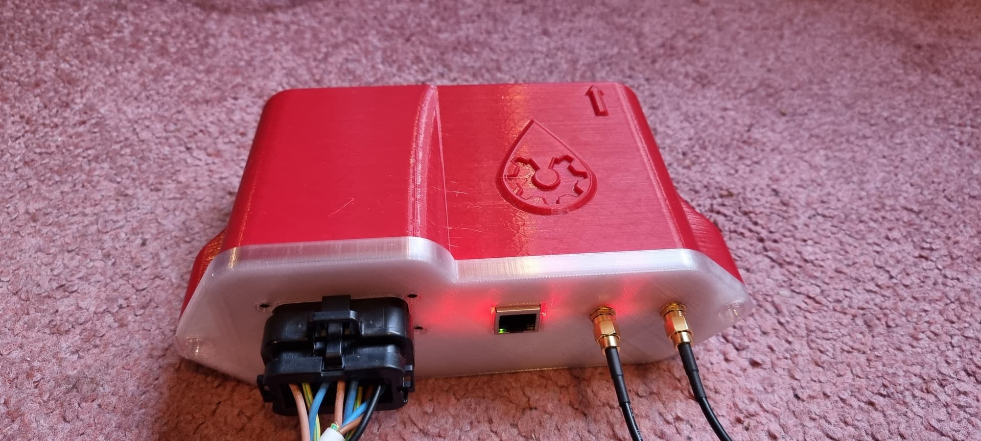
Could you add a hole to the case cap and glue on a plastic cover to see the LEDs? Or would that cause other problems?
I wonder if it would be sufficient to add holes in the case cap and then fill the holes with hot glue. Like a window made of hot glue.
The Google drive links at the top of the page have been updated with the latest fixes.
Only remaining change is to redo the board layout to make the traces to the Cytron heavier for the higher amperage motors.
It will be later in the winter before we have time to make that change.