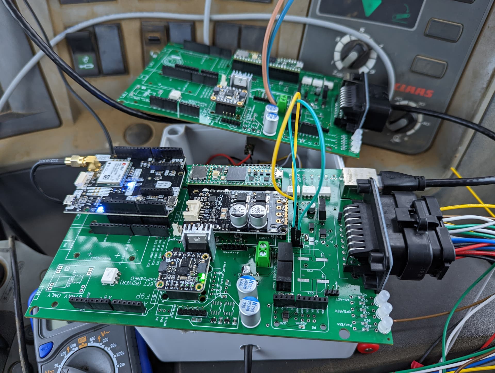
Both AIO PCBs are behaving the same!
One of the heatsinks rattles so that’s almost certainly shorting.
Both AIO PCBs are behaving the same!
One of the heatsinks rattles so that’s almost certainly shorting.
Where can I find the F9P program and installation instructions? AIO, teensy, one standard F9P, BNO085.
The sofware to load the f9p is at Ublox site. The program is Ucenter, and is a free download.
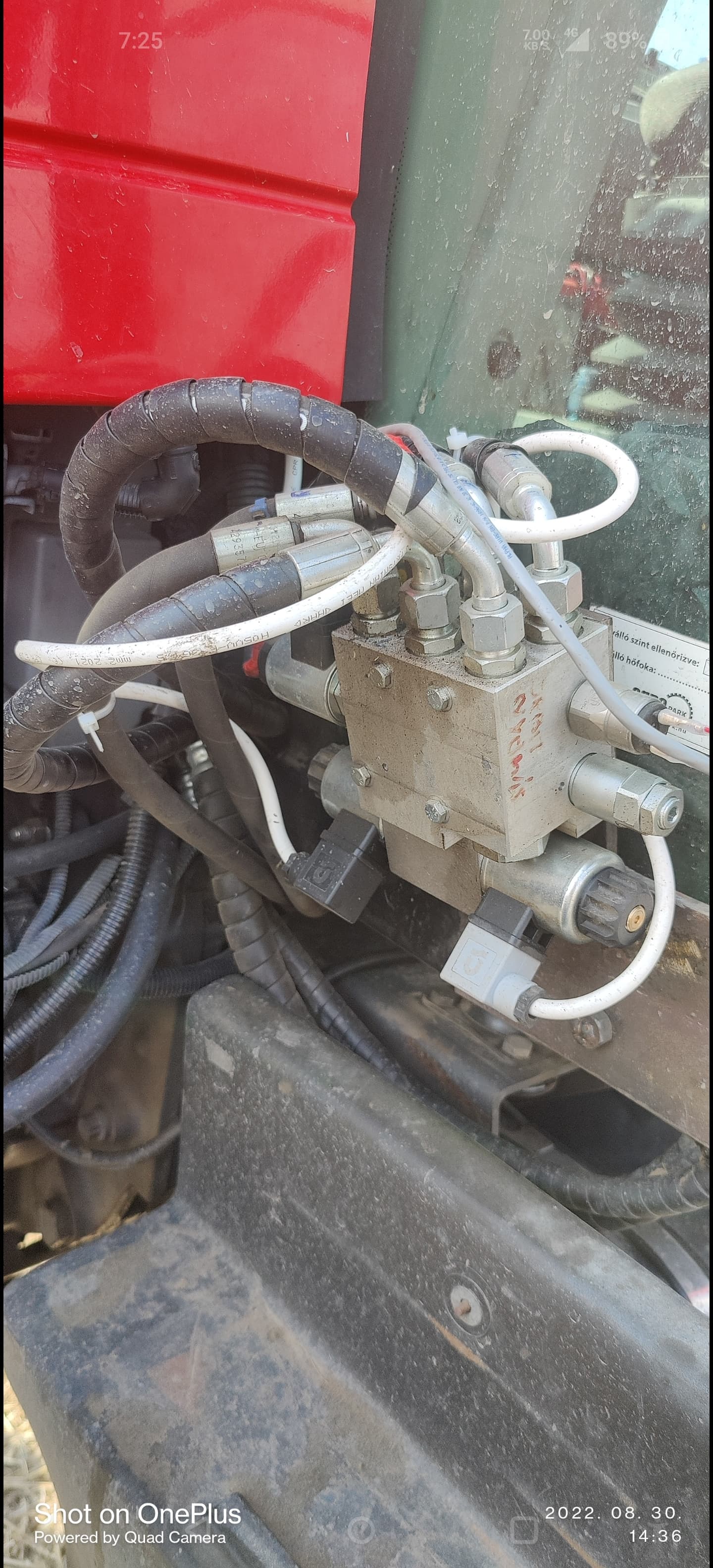
I use Baraki hydraulic valve blocks. pcb can be sufficiently electrically served or should separate wires be drawn directly to cytron and switch fet?
No need for wires with a valve. Just use as is. PCB is sufficeint for most motors as well.
what firmware do you have upload ? i think i have this problem thanks
Try this:
Autosteer_gps_teensy_v5_5.zip (44.2 KB)
thankyou now my leds shine
If anyone is wanting to do another group buy in January, please send me an email with the amount of
Micros and ANN-MB antennas you want.
Once we have enough, I will request another purchase code.
Thanks
Hello I have been away from following this thread due to harvest and other matters. Has this all in one PCB been finalized with all updates completed? Has this been uploaded to GITHUB like others or where does all of the sketches and files reside? are they only in the Google drive at top of thread? Sorry for asking such basic questions. Thanks in advance for any direction as I would like to move to this all in one.
It is not on GitHub at the moment, so use the Google drive link on the first post of this thread.
If you read through this thread you will find most of what you ask.
Jake has updated with fixes and you will see the boards are now version 2.5.
The only thing as I understand at the moment is the traces for the Cytron will be made larger to accommodate larger motors, but this is unlikely to be until the new year.
There are several ways you can get around this, either by putting screw terminals on the Cytron so the motor load never travels through the PCB or by soldering on wires on the bottom side of the PCB.
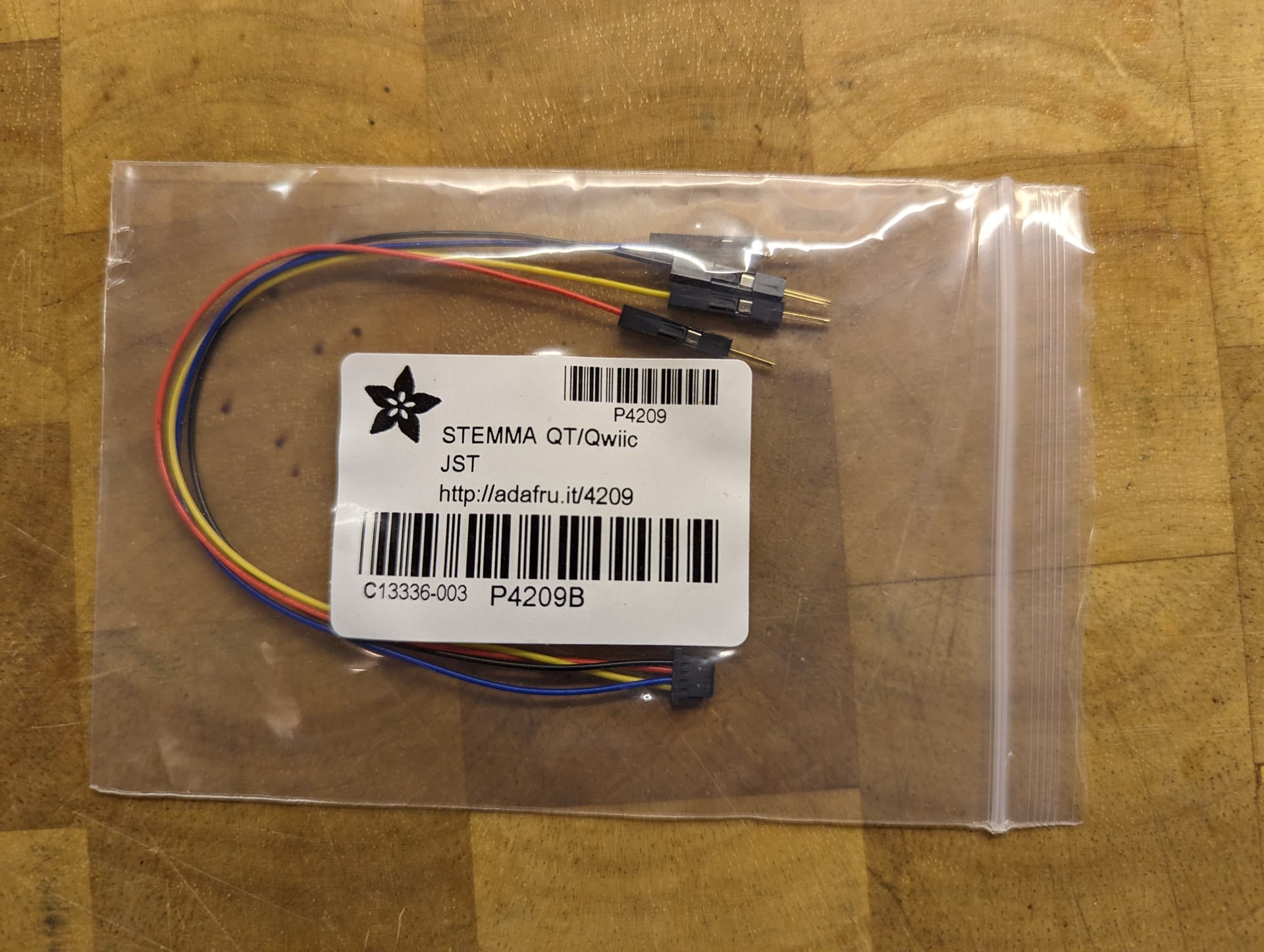
will Imu have a qwiic connector as was on the Kaupoi pcb? it would be very useful.
There are headers soldered so you could use a Qwiic connector into the IMU with male pins on the other end to plug into the PCB headers.
This is the cable you need:
U20 PWRM-TH_K7803-1000 is missing from the BOM file.
Edit: On the Micro AIO
U20 on the Standard board is the ADS1115.
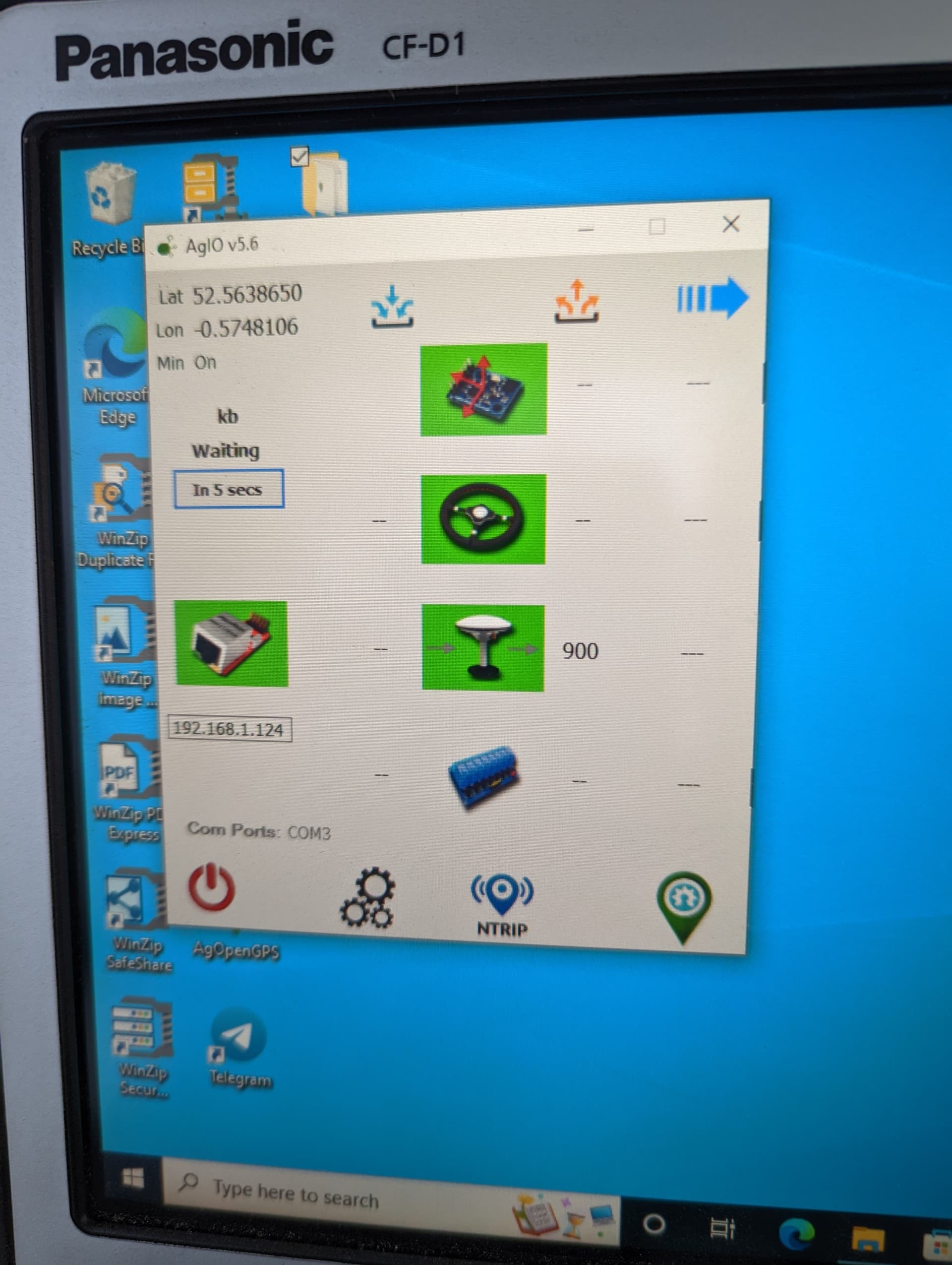
Hello. Tell me where you can see if the VTG is working in the program. 5.6.15
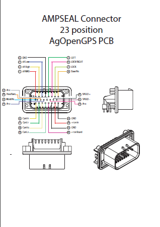
AMP_Connector.pdf (193,2 KB)
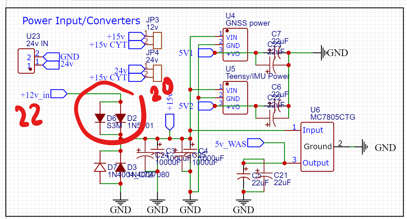
I’ve just realised I was powering the board through 22/12V-in… oops! Guess that should be a “clean” supply for cytron etc and the board is better powered through 20 ?
you did it the right way. 22 is good for powering the board. there’s a diode between 22 and 20. if you happen to confuse + and - using 22/23 for the supply, the board is protected (I can tell since I tested this by mistake ![]() ). if you use 20 instead then current could flow the wrong way round if you confuse + and -
). if you use 20 instead then current could flow the wrong way round if you confuse + and -