That saves me a re-wiring job, thanks ![]()
Ok so we want to power the board through pin 22. That answers one of my questions That’s great to know. Only thing I want to know now is, what is pin 20 actually used for then?
I use pin 20 to power an inductive NPN proximity switch that enables autosteer.
it could also be used to power a 12->24V converter for the cytron. cross sectional area of the PCB traces is yet to be increased though
So in other words, it’s meant for 12v output from the board, not 12v input?
The proximity switch is ok, But using the +15V output on pin 20 to anything more than 2A would not be a good idea (3A include what the board itself use for teensy and F9P).
When you power the board on 12V in(pin22), then everything on pin 20 must go through diode D2 through hole or the D6 Surface mount, which are 3A.
It would be OK to power (from +15V) a outside relay that get 12 V direct from battery.
If you power board on pin 20 (+15V) then there is no reverse polarity protection.
If Cytron need high ampere, then use the 24V in, for either 12V or 24V (going to the 15VCYT)
1 Like
I’m using it for supplying 12V WAS (Ratiometric type one)
When uploading the new V2.5 file onto JCLPCB it comes up in the view PCB image as showing V2.4 on the PCB, i assume this is still correct even though it shows the older PCB version?
If you mean the text on the board, yes. I forgot to change it in my haste
V2.5 is the only one that is posted in the google drive links
1 Like
Hello all,
Has anyone used the new all in one board with Delphi WAS? I can not get mine to work. I tried a different board and a different was and it still doesn’t work.
Are the bugs reported in the standard versions already fixed?
1 Like
make sure GND pins are properly soldered to the board (through all layers). this solved my problem with a delphi WAS
It is just so weird, as soon as I connect the WAS the voltage drops to 3.1v instead of 5v that is supposed to go to the WAS.
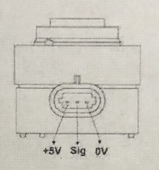
Yes, I connect 5v to pin 1 on the ampseal and Signal to pin 2, Ground to pin 3. Is that correct?
If you look up in this thread a couple days where Vili posted the pinout for the amp connector you will see that pin 3 is was low. Pin 4 is ground
Okay, got it working now. Thank you so much for the help.
Maybe a tip, just found out that 0 to 5v pressure sensor not working on all in one board.
This is because this is a different circuit then on Pcb version 2. So only the 4 to 20mA pressure sensor works.
Hello Vili, do you also have a drawing of the Hammond end plate suitable for the Micro Ampseal board? Thanks
MicroAMP_2_3_Slot_v1_1.pdf (78,5 KB)
1 Like
Whether it’s the standard or micro PCB if we have a single antenna, on which side should we put the f9p? right or left? is there a preference?